Semrock Optical Filters
In applications such as multiphoton fluorescence and second-harmonic-generation (SHG) imaging, a near-infrared laser with short pulses is used to excite the sample. The most common laser is a tunable, mode-locked Ti:Sapphire laser with pulses of about 100 femtosecond (fs) duration. Because nonlinear-optical effects are strongly dependent on the peak intensity of the laser pulse, the most efficient imaging occurs when pulse broadening – and the accompanying decrease in peak intensity – is kept to a minimum. For example, the higher the peak pulse intensity for a given pulse energy, the deeper into a sample it is possible to image.
Pulse broadening is caused by dispersion associated with the optics used to direct and focus the laser light onto the sample, including mirrors, lenses, and beamsplitters. It is always desirable to keep the dispersion of these components to a minimum. But, for the most demanding applications, additional optics are used to compensate the dispersion – in this case it is imperative that the dispersion of the system components be as smooth and slowly varying with wavelength as possible, regardless of the actual magnitude of the dispersion.
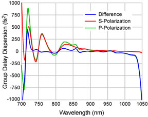
Semrock's BrightLine FF670-SDi01 and FF720-SDi01 short-wave-pass dichroic beamsplitters are designed to reflect the excitation laser light toward a sample, while offering exceptional transmission of the returning near-UV and visible fluorescence or SHG signal. The group delay dispersion (GDD) associated with laser light reflected off of these beamsplitters is very low. For example, a 100 fs transform-limited Gaussian pulse experiences less than 2% broadening over the full laser wavelength range for the FF670-SDi01 filter, and much less than 1% broadening over the full laser wavelength range for the FF720-SDi01 filter.
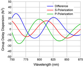
Design spectra of the group delay dispersion in reflection are shown in the graphs below. For the FF670-SDi01 beamsplitter the GDD is designed to be a very smooth curve that varies slowly with wavelength, and remains within ± 500 fs2 between 705 and 1075 nm for s-polarized light, and between 725 and 1040 nm for p-polarized light. Furthermore, the difference between the GDD for s-polarized and p-polarized light is less than ± 100 fs2 between 730 and 1030 nm. For the FF720-SDi01 beamsplitter, the GDD for both s- and p-polarized light, as well as the difference between GDD for both polarizations, is designed to be less than ± 30 fs2 between 750 and 875 nm. The low GDD and small slope of the GDD curve facilitate users who want to compensate for GDD, thus allowing significantly deeper probing into a sample before destroying the sample with excessive pulse energy. Keeping the GDD for s-polarized light approximately equal to that for p-polarized light facilitates users who want to investigate polarization effects.
Group Delay Dispersion (GDD) for FF670-SDi01
Group Delay Dispersion (GDD) for FF720-SDi01
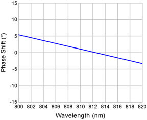
The FF720-SDi01 short-wave-pass beamsplitter is ideal for second-harmonic-generation (SHG) imaging using 810 nm excitation and observation of the SHG signal at 405 nm. In addition to its excellent dispersion properties for minimal pulse broadening, the polarization performance has been carefully designed to maintain linear polarization of both the reflected laser (excitation) beam and the transmitted signal beam for any rotational orientation.
Design spectra of the difference in phase shift associated with s- and p-polarized light are shown below for both light reflected off of (left) and transmitted through (right) the FF720-SDi01 beamsplitter. In both cases the phase shift difference is very low and slowly varying.
Phase shift difference for s- and p-polarized light
reflected off of FF720-SDi01 beamsplitter
Phase shift difference for s- and p-polarized
light transmitted through FF720-SDi01 beamsplitter
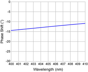
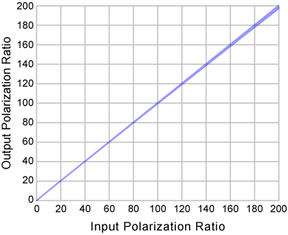
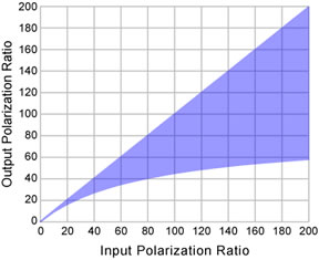
This small phase shift difference, coupled with the nearly identical s- and p-polarized light amplitude values for both reflection and transmission near 810 and 405 nm, respectively, mean that linearly polarized light incident on the filter maintains a very high degree of linearity after reflecting off of or transmitting through the filter. The plots below show how well the linearity is preserved, even for the more difficult case of reflection near 405 nm. The shaded region shows the range of output linearity ratios for all possible rotational orientations of linearly polarized input states of light. The highest output polarization ratio is for nearly perfect s- or p-polarized light input, while the lowest ratio occurs for an approximately equal input mix of s- and p-polarization.
Maintaining linear polarization for light
reflected off of FF720-SDi01 at 810 nm
Maintaining linear polarization for light
transmitted through FF720-SDi01 at 405 nm
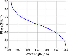
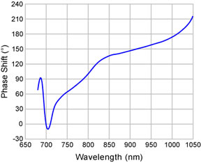
While the FF670-SDi01 beamsplitter is not designed to maintain polarization for any rotational orientation of input light, the phase shift difference spectra are smooth curves that vary slowly with wavelength. As shown in the plots below, for excitation laser light reflected off of the beamsplitter, the difference between the phase shift for p-polarized light and that for s-polarized light is smooth and varies slowly with wavelength between 60° and 180° for wavelengths between 750 to 1000 nm. At any given laser operating wavelength, a waveplate can be used to ensure linear polarization of a desired state at the sample, thus facilitating users who want to investigate polarization effects. For the returning signal fluorescence or SHG light transmitted through the beamsplitter, the difference between the phase shift for p-polarized light and that for s-polarized light is also a smooth curve that varies slowly with wavelength within +/– 60° between 375 and 635 nm.
Phase shift difference for s- and p-polarized light
reflected off of FF670-SDi01 beamsplitter
Phase shift difference for s- and p-polarized light
transmitted through FF670-SDi01 beamsplitter