
Optical Filters FAQs
Here we have provided comprehensive lists of commonly asked questions regarding our Semrock optical filters and related applications. This information is designed to support your inquiries, but if you don’t find the answers you are looking for we encourage you to contact us for further assistance.
Please use the sort buttons in the left navigation to navigate between questions and answers that are specific to Optical Imaging Systems, Fluidics, Cameras, Microfluidics, our Webstore, and Engineering Partnership.
Q: What is SearchLight and how do I use it?
SearchLight is a free spectral modeling tool, and there are many resources for understanding and learning how to use SearchLight.
Q: Which Semrock filter set is compatible with your fluorophore?
Use our Fluorophore Reference chart to match which Semrock optical filter sets are compatible with the fluorophore in your application.
Q: How do you clean optical filters?
Materials Required:
- Latex or Nitrile gloves
- Cleanroom wipes
- Cleanroom swabs in various sizes
- Deionized water
- HPLC grade methanol
- Cloth to dab swab on to remove excess liquid
- Tweezers
- Nitrogen Compressed Air Supply
- Fluid dispenser
Preparation:
- Blow dust off optical filter with compressed air prior to using swab and solvent to clean.
- With gloves on, lay out filters on a cleanroom wipe.
- Even with gloves on, only handle filters by the edges with tweezers or fingers for best results.
General Cleaning:
- Select cleanroom swab size.
- Depress the fluid dispenser to flow cleaning fluid into the top, and touch the swab to the methanol (do not place swab directly into the fluid container).
- Touch the swab to the cleanroom wipe to remove excess liquid.
- Depending upon part size, apply swab to filter using a circular motion for round parts or an S-shaped motion for rectangular parts across the filter surface. It’s important to keep contact with the filter throughout this process.
- Turn filter over and repeat.
- Do not use the same swab side on the second filter side.
Find our demo video, more details on how to clean stubborn debris off optical filters and the do's and don'ts of cleaning optical filters in this how-to guide.
If you have edge blackened optical filters, check out this FAQ.
Q: What is the lifetime of edge blackening paint on a filter, and are there special methods to clean these filters?
The edge blackening paint is intended to remain adherent to the glass surface for the life of the filter, without decomposing and/or falling off, provided that the paint on the filter edge is neither abraded by an external agent nor dissolved using a chemical agent such as acetone. Examples of suitable use include being stably secured in an assembly or housing with no exposure to such solvents. We have encountered no complaints regarding edge blackening paint from customers whose optical systems with edge blackened filters have been in service for over ten years.
Use isopropyl alcohol (IPA) or methanol to clean edge blackened filters, as these solvents don’t affect the edge blackening paint, provided the cleaning is gentle, i.e., not aggressive or of overly long duration. Do not use acetone, as this will remove the paint.
Learn How to Clean Your Semrock® Optical Filters Without Edge Blackening
Q: How can my company check if a filter meets the cosmetic specification?
Each Semrock-brand optical filter shipped by IDEX Health & Science has been inspected and found to pass the relevant cosmetic specifications, using the ANSI or ISO 10110 inspection procedure as appropriate. If the customer wishes to check if a filter meets the cosmetic specification, it is again necessary to follow the applicable cosmetic inspection procedure.
To check a limited number of filters for cosmetics, an RMA can be used to return the filters to the IDEX Health & Science production facility for inspection; the results of the inspection will be shared with the customer.
If filters are to be checked for cosmetics on an ongoing basis at the customer site, the customer must set up an inspection method that is consistent with the appropriate cosmetics standards. Our team is happy to advise on the essential steps and requirements but cannot be responsible for implementing those inspection methods at the customer site.
Establishing such a cosmetic inspection system usually requires the help of someone experienced in this process, who will purchase the relevant standards document, visualization equipment, and comparison standards. This person will then set up a training program for those who will use the inspection system on a day-to-day basis.
Q: What is angle tuning?
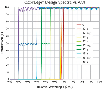
The spectrum of any thin-film filter shifts toward shorter wavelengths when the angle of incidence (AOI) of light upon the filter is increased from 0° (normal incidence) to larger angles. In most cases, the filter spectrum becomes highly distorted at larger angles, and the shift can be significantly different for s- and p-polarized light. The spectral shift that you experience is highly dependent upon filter design. To learn more about how angle tuning affects the spectral performance of different Semrock filters, please review our technical note: Filter Spectra at Non-normal Angles of Incidence.
VersaChrome® Tunable Bandpass Filters
VersaChrome filters are a revolutionary new optical filter technology: thin-film filters that are tunable over a wide range of wavelengths by adjusting the angle of incidence with essentially no change in spectral performance. More information about tunable filters can be found in our technical library.
If you have further questions about a specific application, please contact technical support for assistance.
MyLight™
Try angle tuning yourself, by using MyLight™. Select your filter and click on the blue "MyLight" button above the spectra to model the theory data at whatever angle you desire.
Q: What are AOI and CHA?
Angle of Incidence, or AOI, is the angle at which a collimated beam of light is incident on the filter's first surface, measured relative to the surface normal. Cone half-angle, or CHA, refers to the angular range associated with a non-collimated incident beam, and is measured from the AOI to the largest cone angle.
Changing the AOI or CHA of your incident light will change the spectral response of the filter. For more information on how different types of Semrock filters respond to changes in AOI, please review our technical note: Filter Filter Spectra at Non-normal Angles of Incidence. The spectral response to CHA is dependent upon many factors, so please contact technical support to discuss your specific application.
The AOI and CHA ranges for which filter performance is guaranteed are listed in each filter's Specifications tab on the website. The AOI and CHA specifications given are exclusive; filters may not meet specification when incident light has non-zero value for CHA and AOI.
Q: What is ASCII Data?
ASCII data is typically a text file with two columns. The first column is the wavelength (measured in nanometers) and the second column is the corresponding transmission value of the filter at that wavelength. The transmission value is either on a scale of 0 to 1 or of 0% to 100%. ASCII data is available to download for all filters on the Semrock website. Most filters show actual measured data, while a few filters have theoretical data listed. The legend indicates that the displayed data is either measured or theoretical.
When you are viewing a filter's details you will find a link to the ASCII data for that filter to the right of the graph. Click on ASCII Data to save a copy of the text file that can be used to graph the filter's spectra.
If you need theory data on a single filter, use the blue MyLight button found above the graph and model your theory data, as well as download your ASCII data.
Q: What is bandwidth?
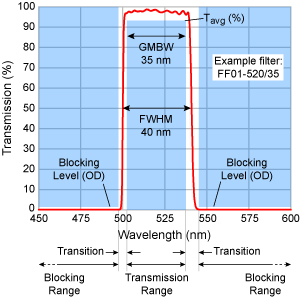
Semrock uses a “manufacturable specification” approach to define the bandwidth of our BrightLine® bandpass optical filters. We believe this approach more accurately reflects the performance of the filter in an optical system.
As shown in the diagram, the filter spectrum (red line) must lie within the unshaded regions. The average transmission must exceed the specification Tavg (%) in the Transmission Region, which has a certain center wavelength (CWL) and a width called the Guaranteed Minimum Bandwidth (GMBW). The filter part number has the form FF01-{CWL}/{GMBW}.
The transmission must lie below the blocking level specifications (OD) in the Blocking Regions. The precise shape of the spectrum is unspecified in the Transition regions. However, typically the filter passband has a Full Width at Half Maximum (FWHM) that is about 1% of the CWL wider than the GMBW bandwidth,
or
FWHM ≅ GMBW + 0.01 x CWL
So, for the example shown in the diagram, the FF01-520/35 filter has a GMBW of 35 nm and a FWHM of 35 nm + 1% of 520 nm, or 40 nm.
Explore Semrock BrightLine® bandpass optical filters in our webstore.
Q: What is Clear Aperture?
.png?sfvrsn=a8c74afa_3)
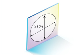
Clear Aperture
Although the optical coating extends to the edge of every Semrock™ filter, the Clear Aperture (CA) dimensions must be less than the transverse filter dimensions.
All filter specifications are guaranteed only within the CA.
The CA dimensions of an unhoused custom-sized filter are as follows:
- For round filters: Greater than 85% of the outer diameter.
- For square and rectangular parts: Over an ellipse with major and minor axes greater than 80% of the transverse filter dimensions.
The CA diameter of a housed filter depends on the size and thickness of the housing:
| Housing Thickness | Housing Diameter (mm) | |||
| 12.5 | 25 | 32 | 50 | |
| 3.5 mm | CA = 10 mm | CA = 22 mm | CA = 29 mm | CA = 45 mm |
| 5.0 mm | CA = 10 mm | CA = 21 mm | CA = 29 mm | CA = 45 mm |
This information is also found on the Specifications Tab for each individual filter.
Q: What makes an optical filter custom?
A filter requires a new coating run if it meets any of the following criteria:
- New design
- Spectral modifications (Any change that would cause current coated stock to FAIL when checking against the new specifications)
- Mechanical modifications, i.e., change to the glass thickness, material, or properties (Wedge, TWE, Flatness)
Click here for our full "Customizing Catalog Optical Filters Guide"
Click here to download a PDF Version of our "Quick Reference Guide"
| Custom-sized Catalog | Semi-custom | Fully Custom | |
|
|
| |
| Examples |
|
|
|
| Spectral Specifications |
|
|
|
| Substrate Material, Thickness, and/or Specifications (Wedge, TWE, Flatness) |
|
|
|
| Dimensions |
|
|
|
| Corner cuts |
|
|
|
| Dimensional Tolerances |
|
|
|
| Clear Aperture |
|
|
|
| Part Marking |
|
|
|
| Cosmetic quality, edge chip and bevel specification |
|
|
|
| TWE, Flatness, RWE |
|
|
|
| Packaging and Package Labeling |
|
|
|
| QC Data |
|
|
|
Q: How do I go about purchasing a custom filter?
If you would like a quote on a custom filter, please fill out our Custom Optical Filters Request form.
Our high-volume, IBS sputtering technology provides unsurpassed performance, repeatability and value. Our designers will meet your optical filter needs and also add value in other areas, such as optical cell design and measurement platforms. From prototype through production, you can count on us for expert design advice, unsurpassed performance and rock-solid reliability. To learn more about how you can benefit from our experience, contact Semrock's technical support or call 866-SEMROCK to discuss all of the available options.
Q: How to custom size a filter?
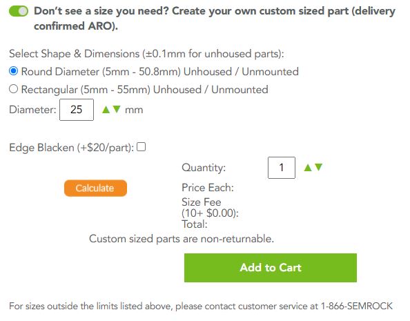
IDEX Health & Science offers custom sizing of most Semrock brand catalog filters right on our website. Whether you need an unhoused / unmounted round or rectangular filter, or the filter mounted into one of our standard-size aluminum housings, use our custom sizing tool to calculate the price for the quantity you require and part number and add it to your cart to purchase.
Simply input your required dimensions:
- Whole millimeter sizes between 10 to 40 mm for round parts are available using the customer part builder. In addition, you can choose 12.5, 12.7, 21.8, 23.3, 25.4, 50 and 50.8mm. IDEX Health & Science also carries standard-size aluminum housings for the following dimensions: 12.5mm, 25mm, 25mm Sutter Threaded Rings, 32mm, and 50mm.
- For rectangular part, it is ranging from 5mm to 55mm. Please note that the maximum ratio of dimensions for custom parts is 5:1.
Each filter which is available for custom sizing lists the dimensional range which can be accommodated for that filter on the product page. The substrate thickness and tolerance will be the same as for the standard size part for the filter of interest, simply click on the Specifications tab for details.
Need to have that 31.4mm unmounted diameter? We can accommodate that as well, please fill out the custom request form and we will get back to you as soon as possible. Our inside sales team will quote the lead time with your order acknowledgement (typically four weeks).
Q: What is filter orientation?
Orientation of Semrock Filters
Because of the durability of Semrock filters, you can easily populate filter cubes, filter sliders, and filter wheels yourself without fear of damaging the filters. To maximize intended transmission and blocking and to minimize autofluorescence, filters must always be oriented so that light is incident on a specific surface of the filter. This note describes the correct orientation for the different filter types.
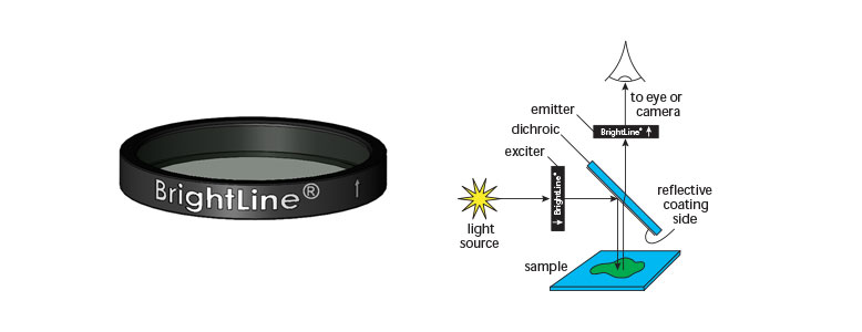
Orienting Housed Excitation and Emission Filters
Semrock exciter and emitter filters mounted in housings feature an alignment arrow on the housing; see the illustrations below. Orient such a filter so that the arrow points in the direction of light propagation. For microscopes, the exciter filter arrow should point away from the light source and toward the dichroic beamsplitter, and the emitter filter arrow should point away from the dichroic beamsplitter and toward the eye, detector, or camera.
Dichroic beamsplitters are rarely mounted in housings. See below for guidance.
Orienting Dichroic Beamsplitters and Other Unhoused Optical Filters
Dichroic beamsplitters and other unhoused optical filters feature orientation marks that identify the coated surface upon which light must be incident. An orientation mark is placed either on the front surface of the filter, or on the edge of the filter as a caret (^) mark. The different types of orientation marks are shown in the following drawings along with the corresponding orientation guidance.
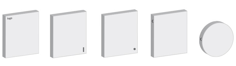
- Semrock logo: The logo is on the surface facing the incident light.
- Line: A short line is on the surface facing the incident light. The line may be easier to see if viewed at an oblique angle.
- Dot: A small dot is on the surface facing the incident light. The dot may be easier to see if viewed at an oblique angle.
- Caret: A caret on the edge of the filter points in the direction of light travel. When the viewer faces the surface that receives the incident light, the caret points away from the viewer.
Caution: A number of dichroic beamsplitters have coatings on both surfaces. Always use the above instructions to identify the coated surface that should face the incident light! If you encounter any ambiguity or difficulty, please contact Semrock for assistance in identifying the surface orientation.
Further Resources
Complete how-to instructions for microscope cube assembly are available in PDF format and video.
Q: Understanding filter, substrate, and housing thickness
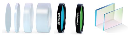
Semrock offers two categories of individual catalog sized filters: unhoused filters such as dichroic beamsplitters, mirrors and tunable filters, or housed filters mounted in black anodized aluminum housings. Housed filters include bandpass filters, edge filters, and some dichroic beamsplitters. For an unhoused filter, the unmounted filter thickness and unmounted substrate thickness are identical. For a housed filter, the mounted filter thickness and unmounted substrate thickness are different, because the mounted filter thickness is the same as the housing thickness.
Each housed filter is available in a standard housing thickness, either 3.5 mm or 5.0 mm. The 3.5 mm housed filters are typically used as emitters when part of a filter set; the 5.0 mm filters are most commonly used as exciters when part of a filter set. The 3.5 mm thick housings can accommodate substrate thicknesses ranging from 1.05 mm to 2.0 mm; the 5.0 mm thick housings, from 1.05 mm to 3.5 mm.
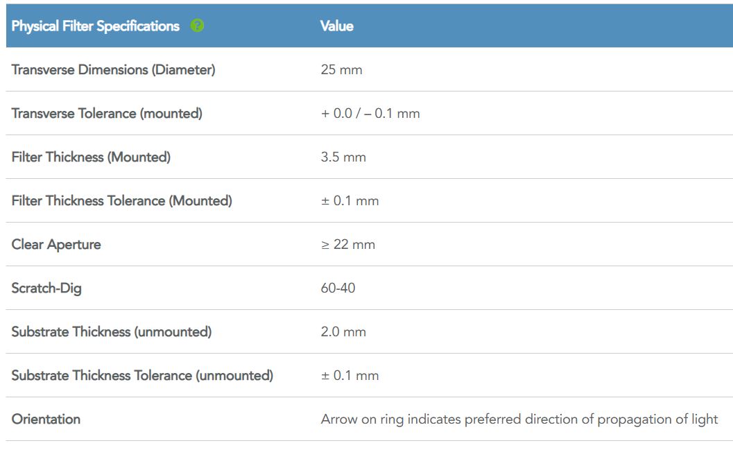
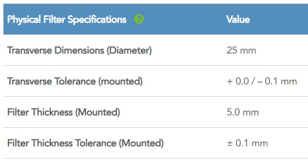
The size of each filter mounted in a housing as a standard catalog configuration is shown on the Specifications tab (see below) under Physical Filter Specifications as “Transverse Dimensions (Diameter)”.

Take for example the exciter and emitter filters from the GFP-3035D general-purpose filter set. The FF02-472/30-25 Exciter is mounted in a 5.0 mm aluminum housing, as shown below.
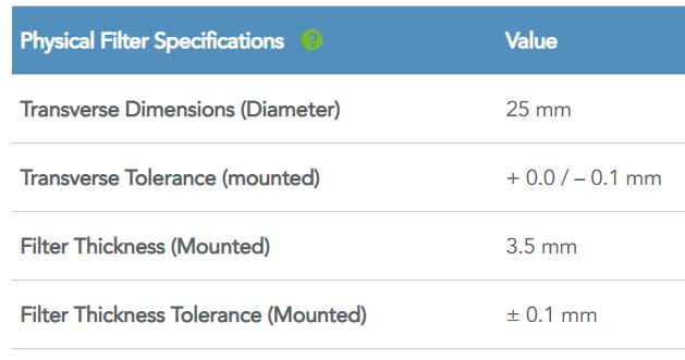
The FF01-520/35-25 Emitter is mounted in a 3.5 mm aluminum housing, as shown below.
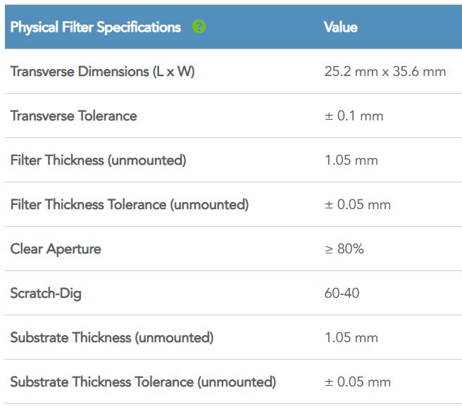
For dichroic beamsplitters and other unmounted filters in a catalog configuration, the size of the filter in the Specifications tab is shown as “Transverse Dimensions (L x W)”.
As shown below, the FF495-Di03-25x36 dichroic beamsplitter of the GFP-3035D filter set has dimensions 25.2 mm x 35.6 mm, has a substrate thickness of 1.05 mm and is unmounted.
Find information about filter thickness, whether mounted or unmounted, unmounted substrate thickness, and dimensional tolerances of filter and substrate thicknesses in the Physical Filter Specifications section of the Specifications tab.
The thickness of a custom sized, unmounted circular or rectangular filter refers to the substrate thickness.
Semrock catalog filters are coated on substrates with standard thicknesses 0.5 mm, 1.05 mm, 2.0 mm, 3.0 mm, 3.5 mm, or 6.0 mm. Before purchase be sure to verify the filter thickness and whether that will be suitable for mount and application requirements.
For questions about filter, substrate or housing thickness, please contact our Semrock optical filters team.
Q: What is flatness / RWE classification?
Wavefront distortion can degrade image quality by reducing contrast or compromising resolution. In several microscopy applications, reducing wavefront distortion is critical to achieving the microscopy method.
IDEX Health & Science offers an extensive and industry-leading range of Semrock brand catalog filters for a variety of applications with specific Flatness / RWE needs. The Flatness Classifications listed in the table below provide an intuitive approach to selecting products of appropriate flatness for a given application.
In determining suitable flatness need for a given application, the most important parameter is often the diameter of the beam striking the dichroic beamsplitter surface. The table below shows the Semrock optical filters best suited to the application, for maximum diameter values. For more specific information, and for other beam diameter value and microscopy examples, the Technical Note and White Paper on this topic [1, 2] provide additional information on RWE, TWE, and microscopy methods, as well as guidance from a system designer’s perspective.
[1] Technical Note: Choosing Dichroic Beamsplitters with Flatness/RWE Appropriate to the Microscopy Method
[2] White Paper: Maximizing the Performance of Advanced Microscopes by Controlling Wavefront Error Using Optical Filters
Flatness/RWE Classification | Example | Nominal Radius of Curvature | Maximum Reflected Beam Diameter, mm | Reflected Wavefront Error at 632.8 nm, PV | Dichroic Family and Example Part Numbers |
|---|---|---|---|---|---|
Super-resolution / TIRF
| TIRF, PALM, STORM, STED
| ~ 1275 meters | 22.5 | < 0.2λ | BrightLine® Laser (Di03-R405-t3-) |
~ 255 meters | 10 | < 1λ | BrightLine® Laser (Di03-R405-t1-) | ||
Image-splitting
| Splitting of emission signal on a pixel based detector
| ~ 1275 meters | 37 | < 0.2λ | BrightLine® Image-splitting
|
~ 100 meters | 10 | < 2λ | BrightLine® Image-splitting (FF509-FDi01-) | ||
Laser | Confocal, combining/splitting laser beams | ~ 30 meters | 2.5 | < 6λ | BrightLine® Laser (Di02-R405-) RazorEdge Dichroic™ (LPD02-488RU-) LaserMux™ (LM01-503-) StopLine® Notch Dichroic (NFD01-488-) |
Standard Epi-fluorescence | Widefield fluorescence | ~ 6 meters | Not Applicable | >> 6λ | BrightLine® (FF495-Di03-) |
Q: What is optical density?
Optical Density (OD) is a convenient tool to describe the transmission of light through a highly blocking optical filter (when the transmission is extremely small). OD is defined as the negative of the logarithm (base 10) of the transmission, where the transmission varies between 0 and 1.
OD = – log 10 (T)
or
T = 10 -OD
Through careful optimization of our measurement equipment and methods, Semrock is able to provide some of the best wide bandwidth Optical Density (OD) measurements possible. Below are typical OD noise floor limitations for most of the measurement data shown on this website.
- For wavelengths between 320 and 1120 nm, transmission values near or below 3e-7 (Optical Density 6.5) are measurement noise limited.
- For wavelengths < 320 nm and between 1120 - 1500 nm, transmission values near or below 3e-6 (Optical Density 5.5) are measurement noise limited.
- For wavelengths > 1500 nm, transmission values near or below 1e-5 (Optical Density 5.0) are measurement noise limited.
Also, for some filters and/or some blocking wavelength ranges, measurements with a noise floor of only about OD 4 are shown.
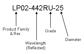
Q: How do we create part numbers for optical filters?
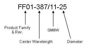
General product naming conventions are as follows:
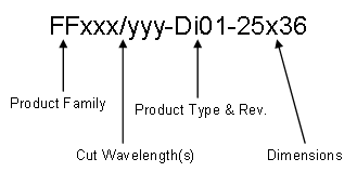
GMBW = Guaranteed Minimum Bandwidth Occasionally there will be an additional ending to the part number after the diameter/dimensions are called out. The addition of a "-D" indicates that a part is unmounted. In this case, the diameter of 25 means that diameter of the glass substrate is 25mm. The addition of a "-N" calls for a part to be unmarked and will not include the Semrock logo, part number, or arrow to indicate the proper orientation.
In the case of a multiband or multi-notch filter, the multiple bands will be called out in an xxx/yyy format, as in this multiband dichroic.
For those parts who have multiple grades available for purchase, the grade is specified in this way:
The following is a guide to help you correlate part numbers and product families. It is not intended for users to create part numbers.
| Abbreviation | Stands For... | Product Family |
|---|---|---|
| AF | Avant Fluorescence Filter | Avant™ |
| BLP | Basic Long Pass | EdgeBasic™ |
| BSP | Basic Short Pass | EdgeBasic™ |
| -D | unhoused, has no metal ring | All |
| Di | Dichroic | BrightLine® |
| E | E-grade filter | RazorEdge®, StopLine®, MaxLine® |
| Em | Emission | BrightLine® |
| FBP | Flow Cytometry Bandpass Filter | Nanopede™ |
| FDi | Flattest dichroic, used for imaging applications | BrightLine® |
| FF | Fluorescence filter | BrightLine® |
| FRET | Fluorescence resonance energy transfer | BrightLine® |
| Hg | Periodic symbol for mercury | MaxLamp® |
| LD | Laser diode | MaxDiode® |
| LF | Laser fluorescence | BrightLine® |
| LL | Laser line | MaxLine® |
| LM | Laser mux | LaserMUX™ |
| LP | Long pass | BrightLine®, RazorEdge® |
| LPD | Long pass dichroic | RazorEdge Dichroic |
| M | Emitter | BrightLine® |
| -N | not marked | Only Diced |
| NF | Notch Filter | StopLine® |
| NIR | Near-Infrared | Near-IR |
| PBP | Polarizing bandpass | Polarizing bandpass |
| QD | Quantum Dot | BrightLine® |
| R | Reflected | BrightLine®, RazorEdge® |
| S | S-grade filter | RazorEdge®, StopLine® |
| SDi | Short-pass dichroic | BrightLine® |
| SP | Short pass | RazorEdge® |
| -STR | Sutter Threaded Ring | All (≤ 2 mm substrate required) |
| T | Transmitted | BrightLine® |
| TBP | Tunable bandpass | VersaChrome® |
| U | U-grade filter | RazorEdge®, StopLine® |
| VLP | Verona Long pass | Verona™ |
| X | Exciter | BrightLine® |
| -Z | ZERO | BrightLine® |
Q: What is pixel shift, and how does the Semrock ZERO option help?
Pixel shift results when a filter in an imaging path (the emitter and/or dichroic beamsplitter in a fluorescence microscope) deviates the light rays to cause a shift of the image detected on a high-resolution monochrome digital camera. This shift becomes problematic when two or more images of the same object are acquired using different filter sets and then overlaid to simultaneously view fluorescence from multiple fluorophores. Images produced by different fluorophores (and different filter sets) will not be accurately correlated or combined because each image is shifted by a different amount depending on the wedge angles found in each filter set. To eliminate pixel shift, BrightLine ZERO™ and Avant ZERO™ filter sets are manufactured and tested to exacting tolerances to ensure accurate image registration when combining multiple images.
The BrightLine ZERO™ and Avant ZERO™ options guarantee that the worst-case image shift when interchanging Semrock ZERO sets will be less than ± 1 pixel, measured relative to the mean image position for a large sample of filter sets, and assuming an 8 μm square pixel.
![]()
The above schematic of a typical epifluorescence microscope shows how filter wedge causes pixel shift.
![]()
Composite images produced from conventional filter sets (above left), which typically have significant pixel shift, are distorted, whereas in this example the BrightLine ZERO pixel shift filter set (above right) yields precisely registered multi-color images.
Technical Note: Pixel Shift in Fluorescence Microscopy
White Paper: Physics of Pixel Shift
Q: What is polarization?

When light is incident on an optical filter at a non-normal angle of incidence, the polarization of the light can be described by two orthogonal vector components associated with the orientation of the electric field of the light wave. The polarization is referenced to the “plane of incidence,” or the plane that is parallel to the normal to the surface of the filter and contains both the incident and the reflected light rays. The polarization component that is perpendicular to the plane of incidence is called the “s” component, and the component that is parallel to the plane of incidence is called the “p” component.
Learn More in our white paper on, "Understanding Polarization"
Q: What are limitations of conventional spectral measurement?
Why might a customer’s filter spectrum measurement differ from the Semrock spectrum?
Commercially available spectrophotometers are optimized for specific scientific and industrial applications. Because their designs have been constrained by price and performance requirements, most commercial spectrophotometers have insufficient precision to accurately measure the spectral characteristics of high-performance optical filters, especially filters with steep spectral edges and deep blocking, which are Semrock hallmarks. Functional limitations in light sources, detectors, and diffraction gratings, and in their combined performance, can create artifacts in the spectral measurement of such high performance optical filters. A customer's filter spectrum measurement may differ from the measurement performed at Semrock due to the presence of these artifacts. Understanding the origins of such measurement discrepancies enables inference of the filter’s actual performance and provides guidance for decision making.
- Feature Rounding
The spectral features of an optical filter often appear rounded when measured using a conventional spectrophotometer. This artifact occurs when the probe beam is not strictly monochromatic. The slight spectral width of the probe beam causes a "smoothing" effect that rounds sharp transitions. In the graph shown here, feature rounding has softened the transition at the beginning of the transmission band. - Noise Floor
A light detector has a sensitivity limit beyond which it cannot report variations in light intensity. This cutoff level sets a limit to the highest optical density (OD, defined as -log10(T)) that a spectrophotometer can measure. The measured OD may, therefore, appear lower than the actual filter performance. When illuminated by light levels below the sensitivity limit, the detection system will report zero signal, but will also report any noise originating within the detector. On a graph this appears as a "noise floor" that corresponds to the highest OD measurable by the spectrophotometer. In the figure, the noise floor is the “noisy” spectral region at the lower left corner of the graph. The noise floor may be wavelength-dependent because of variations in both the light source spectrum and the light detector spectral response. - Sideband Artifact “Kink”
A conventional spectrophotometer sometimes reports a "kink" in the spectrum when measuring a filter with an extremely steep transition between blocking and transmission. In the figure, the kink is the point at which the spectrophotometer measurement diverges from the design spectrum. If present, the spectral kink usually appears between OD 2.5 and 4.5, and can give the impression that the filter's spectral transition is less steep than the actual filter performance. The kink occurs because imperfections in the diffraction grating can create noise sidebands in the spatial profile of the probe beam. If a probe beam has significant sideband noise, and if the filter has a very steep edge, then the light from the noise sideband may transmit through the filter's passband even though the filter has blocked the primary portion of the probe beam. The unwanted transmission lowers the measured OD at that wavelength, creating the characteristic “kink” in the sideband.
For further information on the process that Semrock uses to guarantee filter performance, download our white paper, Advanced Spectral Measurement Systems and Semrock Optical Filters.
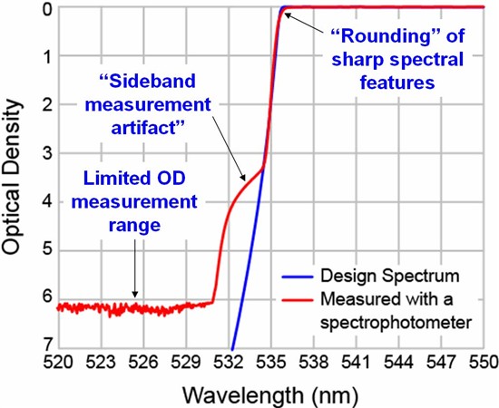
Example showing design and measured spectra of a Semrock LP03-532RU-25 RazorEdge® filter. The measurement was made using a commercial spectrophotometer
Q: What are Sutter threaded rings?
An integrated filter wheel mounting ring for optical filters that is threaded to match the openings in a Sutter filter wheel hub.
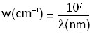
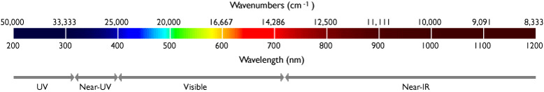
Q: What are wavenumbers?
The "color" of light is generally identified by the distribution of power or intensity as a function of wavelength. Sometimes it is convenient to describe light in terms of "wavenumbers," where the wavenumber (w) is simply equal to the inverse of the wavelength and is therefore proportional to frequency.
Wavenumbers are often used in Raman spectroscopy since the separation of a particular Raman line from the laser line is fixed by the molecular properties of the material and independent of which laser wavelength is used to excite the line. This means that the shift is of constant frequency, regardless of excitation wavelength and can be conveniently expressed in terms of wavenumbers.
To learn more, please review our technical note, "Measuring Light with Wavelengths and Wavenumbers".
Q: How do you choose which optical filters to use in your application when observing cells with a given fluorophore?
Use SearchLight™ to find and model filters with a given fluorophore.
Q: Can you combine two filters within an optical test set-up to achieve deeper blocking?
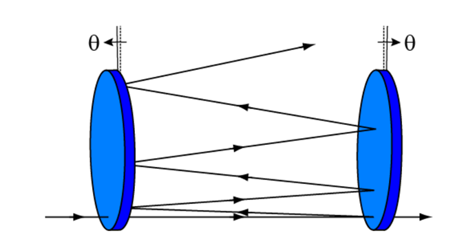
One way to combine two filters for deeper blocking is to slightly tilt the filters relative to each other. Interference filters reflect rejected light, so the slight tilt ensures the rejected light is reflected out from between the pair of filters.
To learn more about combining filters, we have a presentation on “Coherence and Combining Filters”