
Stories & Features
A single-point fluorescence detector measures the total integrated signal independent of the spatial light distribution. The most important filter specifications to consider are the levels and ranges of the transmission and blocking regions. If only a single fluorophore is to be used, a long-wave-pass filter rather than a bandpass filter can be used to maximize signal. However, this usually increases noise (background signal) even more, so is not an optimal choice.
Many systems use several emission wavelength bands detected either simultaneously (multiplexed) or serially, with dichroic beamsplitters used to move the light towards the correct bandpass filters. In these cases, crosstalk can become an issue between spectrally adjacent and overlapping fluorescent channels (Figure 1). The excitation and emission filters work together with the illumination and detection strategy to provide adequate blocking in these systems. Unless a pulsed illumination strategy is employed, emission filters’ transmission regions are narrow enough to be positioned between excitation bandpass regions and with deep blocking on both sides of the emission spectrum to minimize crosstalk from both directions.
Learn more about choosing filters for fluorescence multiplexing here
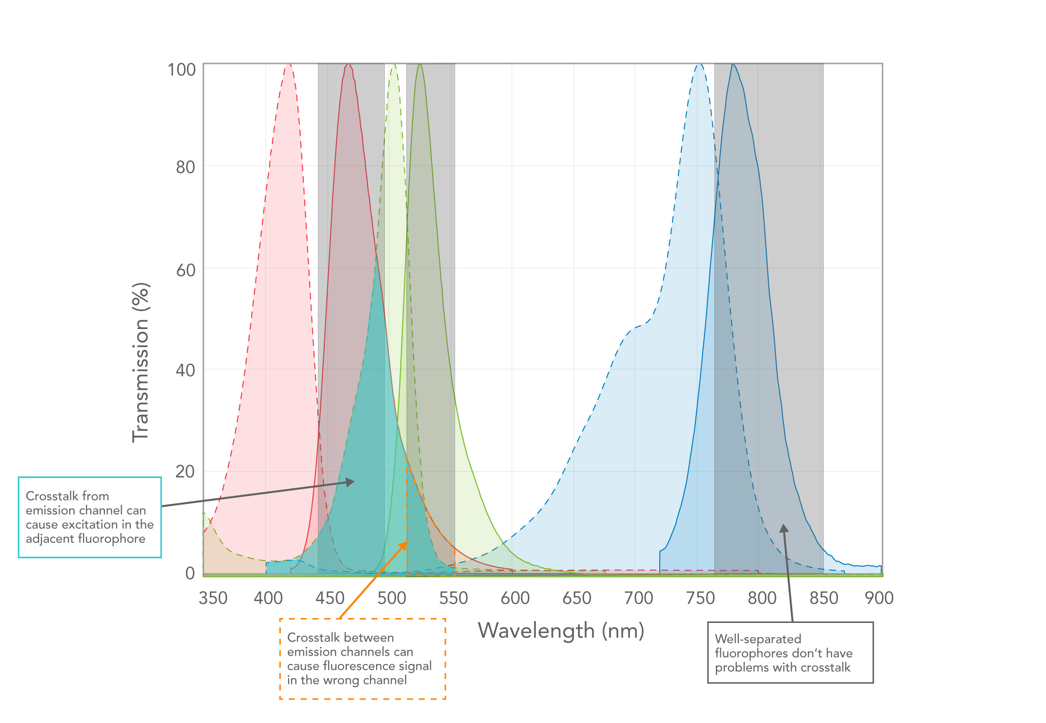
Figure 1: Image showing crosstalk between emission channels.
High OD blocking in the emission filter is required to minimize excitation light from one or multiple bands leaking into the detection channel(s). In addition, the blocking region should extend across the entire spectral response curve of the detector. The blocking should be maximal (i.e., OD > 6 or even > 8) where the excitation light is the brightest, i.e., at the peak laser or LED emission wavelength(s) and in the excitation filter’s transmission band.
At the crossover point (the wavelength at which the spectral responses of the excitation and emission filters intersect) each filter should exhibit blocking of least OD 3.5 and have very high edge steepness. OD values in excitation and emission filters are usually additive, so an excitation filter with OD 3.5 and an emission filter with OD 3.5 at the same wavelength yield an effective blocking of OD 7. As described above, the emission filter’s blocking range should also cover the detector response curve. For instance, in Figure 2, the detector response curve extends out to 750 nm.
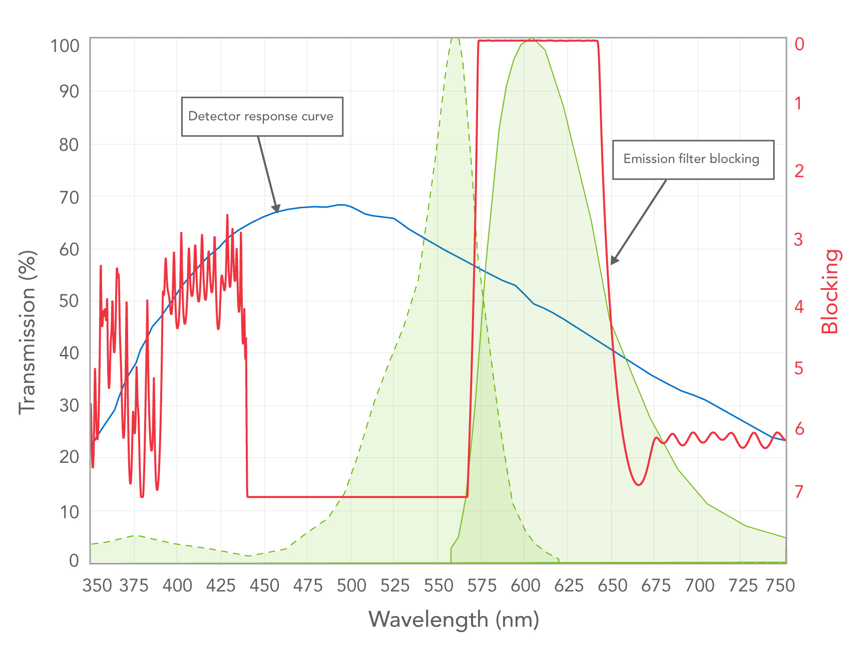
Figure 2: Overlaid spectral responses of detector, fluorophore excitation and emission, and emission filter (in OD).
Interference filters produced by a sputtering process can contain significant surface stress in the deposited films resulting in spherical aberration and wavefront errors. If a sputtered emission filter is used in the typical transmissive configuration, transmitted wavefront errors (TWE) of up to several waves per inch do not affect the integrated signal being measured if the entire beam is captured by the detector (Figure 3), as for a single-point measurement the spatial distribution of the signal is not important.
Although less common, reflection by the emission filter can be used as part of the detection path, essentially using the emission filter as a dichroic beamsplitter. In this case, spherical aberrations can cause significant reflected wavefront error (RWE) that affects the focus of a reflected beam. This can result in over-filling of the detector in downstream measurements. Specifying RWE is crucial in these geometries (Figure 3), unless the aberrations can be corrected in the optical design by refocusing or calibrating the system (Click here to learn more about wavefront errors).
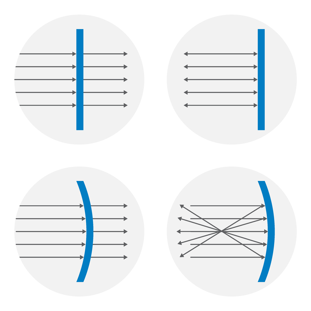
Figure 3: Spherical aberration.
Top: with no TWE or RWE, transmitted and reflected beams are unchanged.
Bottom left: when an optic with spherical aberration is placed in the transmitted beam, a slight increase in transmitted beam width is observed with a small TWE.
Bottom right: the same curved optic causes beam focusing upon reflection, resulting in a higher RWE error.
Choosing the right optical filters is essential for achieving accurate and reliable fluorescence measurements. Factors like transmission, blocking specifications, and the potential for crosstalk in multiplexed systems must all be carefully considered. By selecting filters with high optical density (OD) blocking and steep edge transitions, you can minimize noise and ensure that your detection system is accurately measuring the intended fluorescent signal. Ultimately, understanding how excitation and emission filters work together is key to optimizing your system for both sensitivity and specificity, especially in complex applications.
Learn More About Emission Filters for Fluorescence Detection