Selecting Filters for Fluorescence Multiplexing
Abstract
The steady advances in optical thin film deposition technology over recent decades have enabled production of high performance multiband optical filters that address the increasing demand for multicolor fluorescence instrumentation. Though there is now a wide range of available catalog filters designed for a large variety of fluorophores, selecting suitable filters is often a complex process. Here we present considerations relevant to the design of such a multiplexing system.
For an introduction to the basics of fluorescence filters, click here.
Introduction
The availability of a wide range of cell-compatible fluorescent probes over the visible and near-IR spectrum enables the simultaneous study of multiple cellular components, molecules and/or signals, using several fluorophores in one experiment or assay. Since the usual optical system used for such a study allows only one optical channel to be examined at a time, the system must be extended to allow use of optical multiplexing, i.e., the acquisition of each of multiple probe signals, whether simultaneously, sequentially, or in combination.
Though the best optical performance, i.e., the highest image contrast and lowest crosstalk, is often obtained using single band filter sets and mechanized means to change excitation, dichroic, and emission filters, it is often preferred to improve time resolution at the cost of a modest reduction in performance with the judicious choice of appropriate multiband filters. This article describes how choices are made of sets of optical filters employed in fluorescence multiplexing.
Optical Filters in Fluorescence Instrumentation
Optical filters spectrally select the light passing through the optical system so that the optical output of each fluorophore in the sample can be accurately detected at suitably low concentrations to achieve adequate sensitivity and specificity. This in turn requires the efficient and specific excitation of each fluorophore and low-loss transmission of emitted fluorescence to the detector, while reducing detection of unwanted signals (background).
Most fluorescence instruments use a combination of three filters (Fig. 1). Each fluorophore has its own excitation and emission wavelength band. The excitation filter allows only light over a restricted range of wavelengths within the fluorophore excitation band to reach the sample, blocks light outside that range to reduce excitation of other sources of fluorescence, and blocks light over the emission band. The emission filter transmits light from the fluorophore over the chosen emission band to the detector and blocks light outside this band, especially any excitation light.
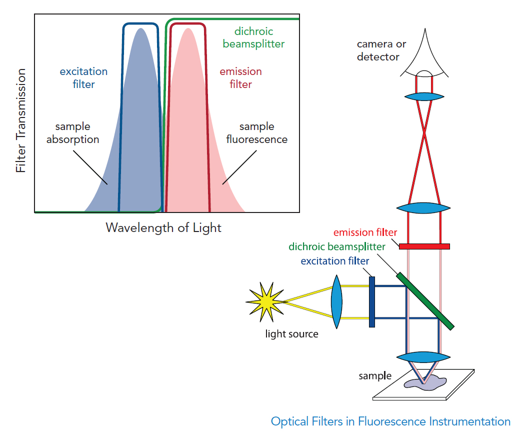
Figure 1. Most fluorescence instruments use a combination of an excitation filter, a dichroic beamsplitter, and an emission filter.
The dichroic beamsplitter is an edge filter positioned at an oblique angle of incidence that efficiently directs light within the excitation and emission bands to their respective destinations.
High performance filters with suitable specifications are critical to maximize the signal-to-background ratio. An excitation filter should have high transmission over a passband at the fluorophore’s peak fluorescence excitation spectrum. An emission filter should have high transmission over a suitably wide emission passband and extended out-of-band blocking to reduce the collection of scattered excitation light and background due for example to autofluorescence. Finally, a dichroic should have an appropriately short transition from high reflection to high transmission levels.
The sets of optical filters in a fluorescence detection system can be highly interdependent. Each excitation-dichroic-emission set must be chosen carefully, not only for suitable results with the corresponding fluorophore, but also for suitable results with the other fluorophores. As different optical filter suppliers have different standards with respect to spectral performance, choosing a set of filters from more than one filter supplier requires greater diligence to prevent suboptimal performance of such improvised filter sets.
Consideration of the optical filters in an instrument is therefore best made early in the design phase, while selecting the fluorophores and defining the system architecture with excitation sources, optical layout, and detectors.
Multi-color Detection and Crosstalk
The filters in Figure 1 are referred to as single band bandpass filters. In fluorescence multiplexing, in which multiple fluorophores are to be detected within a sample, it can be convenient to combine two or more excitation or emission bands on a filter, resulting in multiband filters.
However, use of multiple fluorophores can introduce fluorescence crosstalk (also known as “bleedthrough”) when the spectral profiles of simultaneously excited fluorophores overlap, resulting in emission of one fluorophore into the emission passband of a different fluorophore, and in decreased detection specificity. This may be unavoidable with dense multiplexing because many fluorophores have broad spectral profiles (for example, see Fig. 2). Filter designs with narrower passbands are preferred options in this case. The selections of passband location and width are made to minimize crosstalk without sacrificing overall throughput.
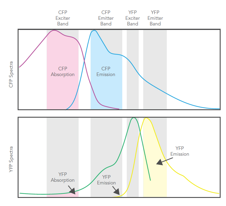
Figure 2. Overlap of spectra for CFP and YFP. A small amount of YFP emission can contribute crosstalk to the CFP channel.
Single Band vs. Multiband
Single band filter sets in multiplexed situations provide flexibility with experimental design and usually achieve the highest contrast and lowest fluorophore crosstalk, but can limit the rate at which complete multi-color images are captured, impairing the capture of sample dynamics. Precise registration of the multiple single-color images can be impeded by the image shift due to small variations in beam direction caused by the filters in the imaging path. Single band filters also increase the number of optical components and their total cost for a higher number of fluorophores.
High performance multiband optical filters allow rapid imaging without sacrificing image fidelity. Three types of multiband filter sets are used for simultaneous multi-color imaging (Fig. 3); each employs a multiband dichroic beamsplitter.
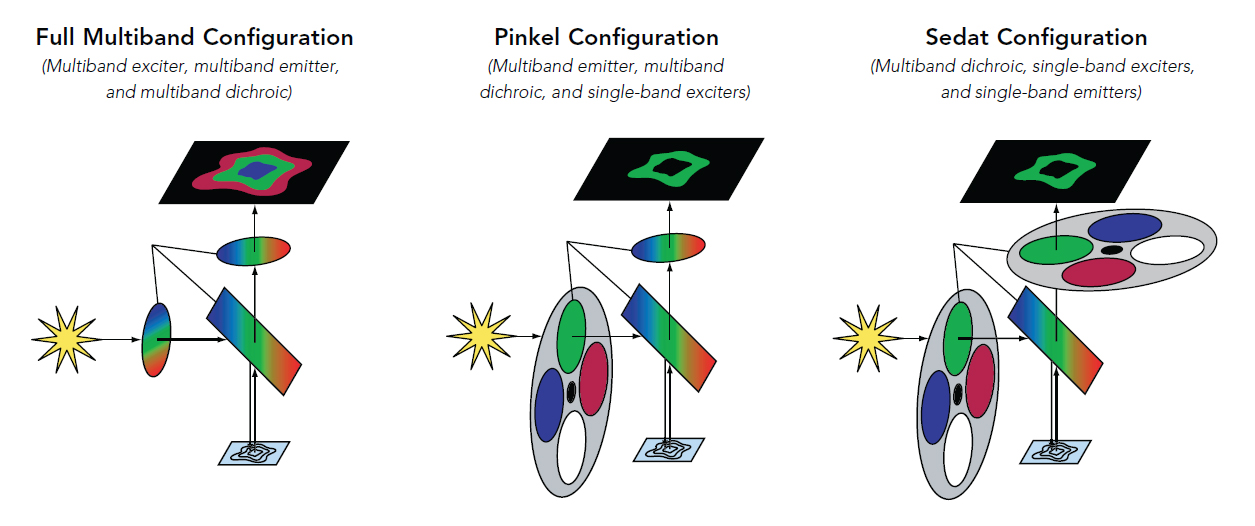
Figure 3. Three types of multiband filter sets.
A suitable tool must be used to numerically model the expected signal, background, and crosstalk for candidate fluorescence fluorophores, light sources, and detectors. These figures of merit can be used to select filters and optionally other components such as fluorophores and light sources. A simple spectral viewer is not sufficient, as it does not allow computation of these parameters. Several such calculators have been developed by individuals; the SearchLightTM system [1] is a freely available alternative.
Single and multiband optical filters and filter sets are available commercially. One can select individual filters to form new sets, but modeling is needed to assure correct function.
Transmission, Blocking, Edge Steepness, and Edge Placement
Hard sputtered dielectric coatings are now standard offerings from most filter suppliers. This technology, when coupled with state-of-the-art deposition control systems and advanced filter design, permits highly optimized complex filter designs to be made in a reliable and reproducible manner, providing new levels of performance, especially for multiband filters. (In this respect we acknowledge the pioneering contributions of Prof. H.A. Macleod, 1933-2021 [2].) Key specifications that distinguish filters include the transmission over the passband, amount of blocking in the blocking bands, edge steepness, and edge wavelength placement accuracy.
The preferred characteristics of excitation, dichroic, and emission filters in terms of transmission over passband and blocking over blocking range are described towards the end of the section “Optical filters in fluorescence instrumentation”. Figure 4 shows the spectra of all three filters designed to optimally work together in a full quad-band set.
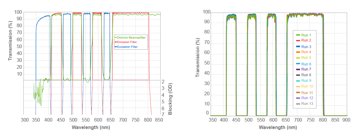
Figure 4. Left: a full multiband set optimized for high transmission and steep edges with deep blocking between bands. Right: High batch-to-batch consistency in the emission filter of the set in the left figure ensures low variability between filters for best performance.
Edge steepness describes the wavelength interval needed for transition between high transmission and deep blocking (or to high reflectivity for a dichroic). Edge placement is the wavelength accuracy with which the spectral edge position is maintained within and between production batches. As discussed below, both these parameters can be chosen to reduce crosstalk between the exciter and the emitter for the fluorophore, and reduce crosstalk from one fluorophore into the other, all without sacrificing overall throughput.
Filter sets with closely positioned excitation and emission passbands are preferred for fluorophores with small Stokes shifts, to excite the fluorophore more efficiently while at the same time collecting most of the fluorescence. The same applies in optical multiplexing; fluorophore spectra overlap, so closely positioned passbands maximize signal while controlling crosstalk. There can however be higher risk for excitation light crosstalk into emission if significant spectral shifts of these passbands occur over different batches of filters during the production phase.
In these situations, high performance filters with both steep edges and precise edge placement are required to preserve signal and background, while reducing crosstalk. Rapid transition from transmission to blocking, combined with control of the wavelength range over which this transition takes place, guarantees deep blocking between bands, even when they are closely spaced. In addition, ensuring that the edges are repeatably positioned as close as possible to the nominal optimum location results in higher system brightness with low and controlled crosstalk.
Finally, precise edge placement with high batch to batch consistency is also critical for reliable quantitative analysis, so that each instrument delivers the same results.
Other Considerations
Wavefront quality may be important in imaging applications, as wavefront distortion can degrade image quality by reducing contrast or compromising resolution. When necessary, optical filters must be selected with low transmitted wavefront error (TWE) over the imaging path, and/or with low reflected wavefront error (RWE) for reflected light. See [3] for detailed discussion of this topic.
The spectral edge of a filter shifts towards the blue with increasing Angle of Incidence (AOI), so one must assess the behavior of a filter if used with a beam having a range of AOI values; this can be an especially useful in compact optical systems whose beams usually have a larger range of AOI values. Consideration of this effect can reduce undesired spectral performance, especially in dichroics, which affect signal and noise.
Finally, filter surface cosmetic quality must be considered, especially in systems that have filters close to conjugate focal planes.
Conclusions
The considerations above provide a strong starting point when designing any fluorescence imaging system, and particularly one with optical multiplexing. In situations where no catalog filters are available, this information is required when designing custom filters.
6. References
[1] SearchLightTM
[2] Macleod, H. A., Thin-Film Optical Filters, Fifth Edition, CRC Press (2021).
Authors
Anne Souchon, Elizabeth Bernhardt, Ph.D., and Michael Delay, Ph.D.