Stories & Features
Of course, fittings are standard items used to connect the components together, using tubing as the flow path bridge between components. Yet, one of the most commonly-asked questions regarding fittings is, “Where do all these fittings go in my system?” In other words, how do I know what to use and where?
One common way to distinguish between fittings is by classifying them based on the pressure they can hold. This narrows the fittings choice based on where in the system they will be used.
Generally, fittings are classified as either “low pressure” or “high pressure” fittings. Correspondingly, “low pressure” most often refers to applications or areas in your system where the flow path pressures do notexceed 1,000 psi (69 bar). “High pressure” areas can have flow path pressures that exceed 6,000 psi (400 bar)! (Some of the differences between high-pressure and low-pressure fittings have already been discussed earlier in this manual.)
In an HPLC system, there are generally three pressurized zones, each with its family of fittings. The first zone exists between the reservoir and the inlet of the pump. This is typically a low-pressure zone, as the pump is pulling the mobile phase from the reservoir in this area, usually creating some negative pressure. The fittings used in this zone are generally low-pressure, low-cost fittings, most often having a 1/4-28 flat-bottom geometry, and are generally for 1/8” (3.2 mm) outer diameter (OD) tubing.
The second zone in the system exists from the outlet of the pump through the injection valve and through the HPLC column. In this zone, the fluid flow is being resisted by the stationary phase inside the column, and as such, the pump experiences higher back pressures...as do the fittings.
In this second zone, fittings are generally classified as high-pressure fittings and most frequently have a 10-32 coned geometry for use with 1/16” (1.6 mm) OD (or smaller) tubing. Because performance demands of the fittings are greater in this area of the system, the manufacturing costs and purchase price of the fittings are generally higher.
Lastly, in the third zone — from the tubing exiting the column through the detector and onto the waste reservoir — the system pressures are generally near ambient pressures, with slightly elevated pressures being experienced when extra components are used (like back pressure regulators, for instance). Because the system pressure in this third zone is typically low, the fittings once again often assume a standard, 1/4-28 flat-bottom geometry, and they are typically for use with 1/16” (1.6 mm) OD tubing.
It is important to note that even though this third zone is a lower pressure zone, many OEM (“Original Equipment Manufacturer”) companies realize that most laboratories have more fittings with the 10-32 coned geometry for 1/16” (1.6 mm) OD tubing than any other type of fitting. Therefore, the receiving ports available on equipment in this zone may require the use of “high pressure” fittings, even though the inline pressures are low.
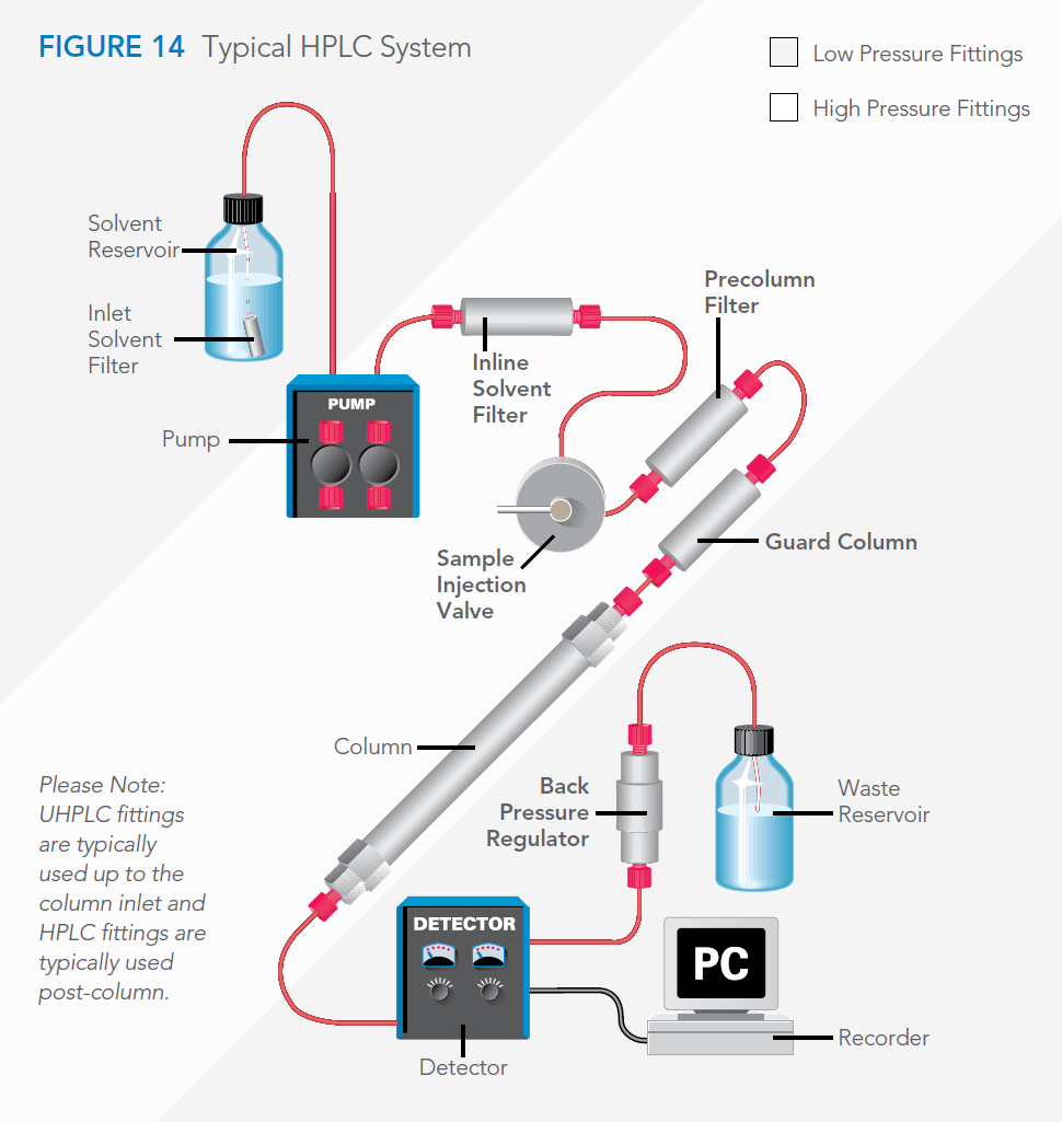
The diagram below shows an “accessorized” HPLC system, to help you understand how a system is put together — including what fittings to put where.