Semrock VersaChrome Tunable Bandpass Filters
 1. Introduction
Thin-film filters are the ideal solution for wavelength selection in most optical systems due to exceptionally high transmission (close to 100%), very steep spectral edges, and blocking of optical density 6 or higher over wide spectral regions for maximum noise suppression. However, until now thin-film filters have been considered “fixed” filters only, such that changing the spectral characteristics requires swapping filters. There are mechanical means to perform filter swapping, like filter wheels, but these are generally large in size, relatively slow (minimum switching times are typically 50 to 100 ms), and they permit only a limited number of filters (typically wheels contain from 4 to 12 slots). Thus, size, speed, and filtering flexibility are all limited.
When higher-speed, more flexible wavelength changing is required, diffraction gratings are commonly used. Gratings permit any wavelength within a range to be selected, and can change wavelengths relatively quickly since only rotation of the grating is required. Thus, gratings are the basis of most scanning spectral measurement systems. However, gratings do not offer very good spectral discrimination – spectral edges are not very steep and out-of-band blocking tends to be poor. Grating-based systems also exhibit limited control over the filter bandwidth. While the bandwidth can be adjusted (usually by adjusting the width of a mechanical slit), the edge steepness decreases as the bandwidth increases. And perhaps the most limiting problem with grating-based spectral instruments is that at least one spatial dimension is required for spreading out light rays in a wavelength-dependent fashion, and thus it is not possible to measure a two-dimensional imaging beam directly with a grating.
Many optical systems can benefit from tunable filters with the spectral and two-dimensional imaging performance characteristics of thin-film filters and the center wavelength tuning speed and flexibility of a diffraction grating. Liquid-crystal and acousto-optic tunable filters and linearvariable filters combine some of these characteristics, but none are ideal and all have significant additional limitations.
Semrock has now developed a revolutionary new optical filter technology: thin-film filters that are tunable over a wide range of wavelengths by adjusting the angle of incidence with essentially no change in spectral performance. Both edge filters and bandpass filters with wide tunability are possible.
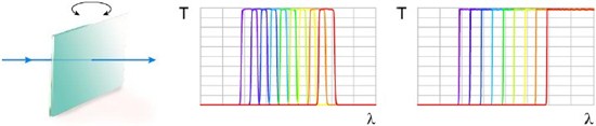
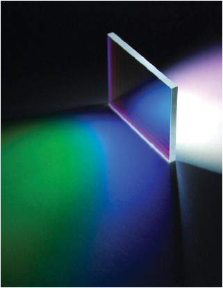
Figure 1: Illustration of tunable bandpass (center) and edge (right) filters resulting from angle-tuning of a thin-film filter (left).
2. Angle-tuned thin-film filters
It is well-known that the spectrum of any thin-film interference filter shifts toward shorter wavelengths when the angle of incidence (AOI) is increased from 0° to larger angles [1]. However, in general the spectrum becomes highly distorted at larger angles, and the shift can be significantly different for s- and p-polarized light, leading to a strong polarization dependence.
Mathematically, when the AOI of light upon the filter is increased from 0° (normal incidence) to larger angles, the resulting wavelength shift is generally described quite accurately by the equation

where θ is the AOI and neff is called the “effective index of refraction,” which is unique for each filter design and for the two orthogonal states of polarization. This effect has been used to tune the spectra of optical filters over a limited range of wavelengths.
As an example, Figure 2 (top left) shows calculated spectra of a multi-cavity Fabry-Perot thin-film filter designed to provide a narrow passband (about 2 nm) at 561 nm. Spectra are shown for s- and p-polarizations, and at AOI values of 0°, 30°, 45°, and 60°. Note that the passband becomes considerably narrower for s-polarization and wider for p-polarization as the AOI increases. Also note that the peak shifts more rapidly for p- than for s-polarization. As a result, at higher AOI values the filter becomes strongly polarization dependent. For this filter example the usable tuning range (before excessive distortion of the spectrum occurs) is approximately 10 to 15 nm, or about 2% to 3% of the starting wavelength.
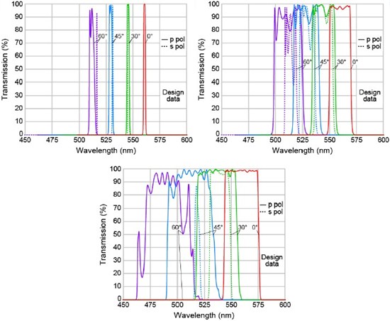
Figure 2: (Top left) Example of a narrowband multi-cavity Fabry-Perot thin-film filter (FWHM ~ 2 nm). (Top right) Example of a wider-passband multi-cavity Fabry-Perot thin-film filter (FWHM ~ 20 nm). (Bottom) Example of a fluorescence bandpass thin-film filter comprised of a combination of long-wavepass and short-wave-pass edge filter coatings (FWHM ~ 35 nm). All spectra are calculated.
Filters of this type are used in a number of commercial devices and instruments for fiberoptic telecommunications test and measurement and system applications. Tuning ranges for these devices are about 30 to 40 nm near 1550 nm, which corresponds to about 2% to 2.5% of the starting wavelength.
For applications not involving precise laser lines or fiber-optic telecommunications, typically wider passbands are desired. Figure 2 (top right) shows an example of another multi-cavity Fabry-Perot thin-film filter designed to have a wider passband of approximately 20 nm full-widthat- half-maximum (FWHM). The behavior is analogous to that of the narrower filter (top left) – the spectrum shifts to shorter wavelengths, becoming increasingly distorted at higher angles of incidence, the passband becomes considerably narrower for s-polarization and wider for ppolarization as the AOI increases, and the peak shifts more rapidly for p- than for s-polarization, all resulting in an increasingly distorted spectrum at higher angles of incidence and thus reducing the useful tuning range of the filter.
Many fluorescence imaging and quantization applications require filters that are still wider – often 30 to 50 nm wide or more (at visible wavelengths). For such wider filters, especially for applications involving incoherent light, it is often more efficient to form the passband using a combination of long-wave-pass and short-wave-pass edge filters. Edge filters are formed from the edges of a “stopband” spectral region that results from an approximately quarter-wave stack of high- and low-index thin-film layers. Figure 2 (bottom) shows an example of such a filter. Note that the this filter exhibits qualitatively similar behavior to the multi-cavity Fabry-Perot type filters, but there is significantly more distortion of the spectrum as the AOI is increased from normal incidence. In fact, the passband ripple becomes intolerable for p-polarization light, and the passband for s-polarization disappears completely for light at higher angles (it is not even visible on this graph for AOI = 60°). Therefore, the useful angular tuning range is only about 10° to 15° for this type of filter, resulting in a wavelength tuning range of only about 0.5% to 1%. For many applications unpolarized light is used, and thus a graph of the filter spectrum for average polarization more clearly illustrates the actual spectral performance. Figure 3 (left) shows average polarization spectra at six angles (ranging from 0° to 60°) for a fluorescence filter similar to the one show in Figure 2 (bottom). The spectrum is highly distorted even at angles of 20° to 30°, and almost unusable for larger angles.
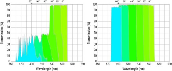
Figure 3: (Left) Example of a fluorescence bandpass thin-film filter comprised of a combination of longwave-pass and short-wave-pass filter coatings (FWHM ~ 35 nm). Six spectra associated with light of average polarization and for angles ranging from 0° to 60° are shown. (Right) Semrock VersaChrome tunable filter shown for comparison. Spectra are calculated.
In contrast, the spectrum of a comparable VersaChrome bandpass filter shown in Figure 3 (right) maintains high transmission, steep edges, and excellent out-of-band blocking over the full range of angles from 0° to 60°. In Section 4 we explain how this performance is possible.
3. Other types of tunable optical filters
There are a variety of different tunable optical filter technologies that have been developed. However, all tend to require compromise in at least some critical performance characteristics in order to achieve tunability, thus demanding a careful analysis of the strengths and limitations of each approach for a given application. As pointed out above, diffraction gratings offer one of the simplest methods to achieve high-speed tuning, but they are not capable of tuning a beam of light carrying a two-dimensional image. Here we limit the discussion to tunable filters for imaging applications, and briefly review three of the most popular alternatives to thin-film filters.
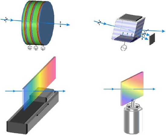
Figure 4: Diagrams of tunable filters capable of transmitting an image-carrying light beam. (Top left) Liquid-crystal tunable filter; linear polarizers are blue, fixed birefringent plates are green, and liquid-crystal plates are red. (Top right) Acousto-optic tunable filter; an RF voltage applied to an acoustic transducer on the bottom of the crystal generates a volume diffraction grating. (Bottom left) Linear-variable filter; tuning is achieved by translating the filter along its length with a stage. (Bottom right) Semrock VersaChrome tunable thin-film filter; high-speed tuning results from a simple rotate on of the filter, like a grating.
Liquid-crystal tunable filters (LCTF): This type of filter is based on a Lyot-Ohman polarization interference filter configuration [2], which is a series birefringent crystal plates separated by linear polarizers (see Figure 4 (top left)). Each “stage” of this filter produces a sinusoidal variation of transmission vs. wavelength, and the combination of many stages each producing a sinusoidal curve with a different frequency results in constructive interference of the overall transmission characteristic at just one wavelength – the filter passband. In a liquidcrystal tunable filter, birefringent liquid-crystal plates are added to the fixed birefringent plates in each section, such that an adjustment of the liquid-crystal birefringence by application of a voltage across these plates modifies the wavelength at which the constructive interference occurs, thus tuning the wavelength of the passband.
Perhaps the greatest advantage of the liquid-crystal tunable filter is the exceptionally wide tuning range – these filters can be designed to tune over many 100’s of nm. In particular, filters are available for tuning over the entire visible wavelength range (< 400 nm to > 700 nm). Like angle-tuned thin-film filters, they are capable of large apertures and two-dimensional imaging. Significant shortcomings of these filters include poor transmission, poor edge steepness and out-of-band blocking, fixed bandwidth, and low laser damage threshold (LDT). And, because they are based on polarization, they are strongly polarization dependent. In fact, they transmit only linearly polarized light, so the maximum transmission of unpolarized light is 50%. Since the transmission of even the passed polarization tends to be about 50%, the resulting overall transmission for unpolarized light often does not exceed 25%.
Acousto-optic tunable filters (AOTF): This type of filter is based on the diffraction of light from a volume grating formed by acoustic shear waves traveling in a single crystal of a material like tellurium dioxide (TeO2) (see Figure 4 (top right)). The waves are produced by a radio frequency (RF) transducer bonded to one side of the crystal. Light transmitted through the crystal is separated into three waves, each traveling in a different (angular) direction: a 0th order undiffracted beam, a diffracted beam of one orientation of (linear) polarization, and a diffracted beam of the other (orthogonal) polarization. The undiffracted beam contains all wavelengths, whereas the diffracted beams contain only wavelengths within a narrow passband due to diffraction off of the volume hologram. To use the device as a filter, usually the undiffracted beam and one of the polarized diffracted beams are blocked, and the second polarized diffracted beam is used for the transmitted light.
Advantages of the AOTF are predominantly its wide tuning range (like the LCTF it is also capable of tuning over 100’s of nm), and extremely high tuning speed (wavelength switching times as fast as 10 μs are possible, compared to ms and above switching times for all other technologies). The most significant disadvantages include poor edge steepness and out-of7 band blocking, lack of adjustable bandwidth, and very small apertures (typically 3 to 10 mm at most), which limits the usefulness for imaging applications. And, like the LCTF, AOTF’s only use linearly polarized light, and thus for unpolarized light applications at least 50% of the light is lost.
Linear-variable tunable filters (LVTF): Linear (as well as circular) variable thin-film filters are based on the concept of nonuniform thin-film layer thickness variation as a function of position along a linear direction (for linear-variable filters) or around the azimuthal direction of a round filter (for circular-variable filters). As a result, the spectral properties of the filter, which scale with the layer thickness, vary spatially as well. Thus, by varying the location of an optical beam on the filter – either by moving the beam across the filter or moving the filter across the path of the beam – the edge position of an edge filter or the passband wavelength of a bandpass filter can be varied (see Figure 4 (bottom left)). A useful configuration of LVTF’s involves two edge filters – one a long-wave-pass filter and the other a short-wave-pass filter – such that when they are translated independently not only the center wavelength but also the bandwidth of the resulting bandpass filter can be adjusted.
LVTF’s share some of the advantages of other tunable thin-film filters, such as high transmission, high laser damage threshold and excellent imaging properties. In addition, because light is always incident at or near 0° AOI they can be polarization insensitive. And using the configuration noted above, the bandwidth can be adjusted arbitrarily for any enter wavelength. Significant disadvantages include poorer spectral performance (edge steepness) due to the variation of the spectral properties across a non-zero width optical beam, and slow tuning speed due to the need to translate the filters mechanically. The limited spectral performance can be optimized for a given system (by trading off lower transmission or spatial resolution resulting from a smaller beam against higher spectral resolution), but in most practical systems the trade-off is significant.
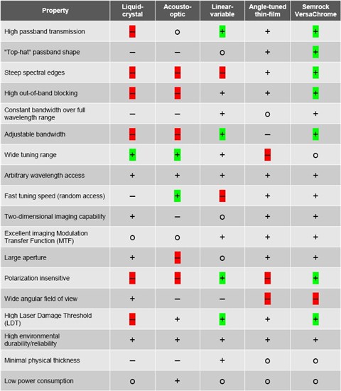
Other tunable filters: There exist a number of other thin-film and non-thin-film approaches to tunable optical filters capable of selecting a band of wavelengths from a two-dimensional imaging beam, including: bulk Sagnac, Mach-Zehnder, and Michelson type interferometers, Fabry-Perot interferometers, and thin-film filters with actively adjustable layers and/or substrate or tuned by mechanically induced changes in the optical properties via the stress-optic effect [3]. Interferometers tend to involve large, complex, and expensive instrumentation not suitable for many applications, while the actively tunable thin-film filter approaches have not yet demonstrated practically interesting performance due to material and/or process limitations. Table 1 compares advantages and disadvantages of the different approaches described here. The most significantly limiting or advantageous features are highlighted in red and green.
Table 1: Comparison of properties for several tunable filter types. In the table, a “+” means the filter type can provide very good to excellent performance relative to the desired property, an “o” means it provides adequate to good performance, and a “–” means it provides limited or poor performance.
4. Why are VersaChrome tunable filters so unique?
As shown in the example in Figure 3 (right), VersaChrome filters maintain high transmission, steep edges, and excellent out-of-band blocking over a very wide range of angles up to even 60°. At the heart of this invention is Semrock’s discovery of a way to make steep edge filters at high angles of incidence with essentially no polarization splitting and nearly equal edge steepnesses for both polarizations. And, remarkably, these properties apply over a wide range of angles. As a consequence, it is possible to tune these filters over the full angular range with little to no change in the properties of the spectrum regardless of the state of polarization of the light passing through the filter. In fact, Semrock’s VersaChrome series of filters are specified with a tuning range of at least 12% of the filter edge or center wavelength at normal incidence!
Figure 5 (top) shows the calculated spectra for both polarizations of light at 4 different AOI’s ranging from 0° to 60° for a VersaChrome bandpass filter. The spectra demonstrate the ability to tune from about 555 nm to 490 nm, or about 12% of the center wavelength at normal incidence, while maintaining high transmission and steep edges regardless of polarization over the whole tuning range. This filter has a FWHM bandwidth of about 30 nm, and the bandwidth remains constant over the entire tuning range.
Figure 5 (bottom left) shows actual measured spectra for this filter at six different angles of incidence ranging from 0° to 60° and both polarization states at each angle. The filter was manufactured using Semrock’s advanced ion-assisted ion-beam sputtering and proprietary optical monitoring processes. Thus the resulting, hard-coated filter exhibits high transmission and excellent environmental reliability and optical durability. The spectra were measured using a Perkin Elmer Lambda 950 commercial spectrophotometer with the resolution set to 0.1 nm. In the configuration used, the light beam at the filter is not perfectly collimated; the cone-half-angle (CHA) is about 2.5°. This range of angles explains the apparent decreasing edge steepness as the AOI increases. The actual edge steepness for collimated light remains relatively constant, but when measuring the filter with probe light that covers a 5° range of angles, there is an averaging effect that occurs resulting in an apparently less steep edge, just as if the filter were measured with a broader wavelength resolution setting on the spectrophotometer. To illustrate this effect, Figure 5 (bottom right) shows the calculated spectra for this filter assuming probe light with a 2.5° CHA. These spectra exhibit almost identical edge steepness values to those found on the measured spectra.
The sensitivity of the edge steepness that is apparent in the measured spectra and the calculated spectra for imperfectly collimated light in Figure 5 (bottom) highlights an important tradeoff that must be considered for angle tuned thin-film filters. To maximize the tuning range
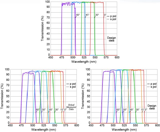
Figure 5: Example of a custom VersaChrome tunable bandpass filter. (Top) Calculated spectra at AOI’s from 0 to 60° for both p- and s-polarizations. (Bottom left) Actual measured spectra using a commercial spectophotometer with a resolution of 0.1 nm and a cone-half-angle (CHA) of 2.5°. (Bottom right) Calculated spectra for the same filter assuming a CHA of 2.5°, demonstrating that the apparently reduced edge steepness at higher angles is an artifact of the non-collimated light.
of a filter for a given change in angle, or to maximize the speed with which a filter can be tuned, it is desirable to make the change in wavelength for a given change in angle as large as possible (equivalent to making neff in
the tuning equation as small as possible). The speed benefits because inertia limits the speed with which a filter can be rotated by a given amount in a given time. For example, galvanometer scanners can operate more quickly over a smaller angular
range. But increased sensitivity of wavelength to angle reduces the spectral resolution (e.g., how steep the edges are) for a real light beam comprised of a non-zero range of angles. Laser-based optical systems typically have regions within the system
in which the light is exceptionally well collimated (typically less than a few milliradians). However, for most imaging systems, the smallest range of light ray angles is often at least ~ 2° or more. In a fluorescence microscope, the CHA in the
collimated space between the objective and the tube lens (where an emission filter is located) is approximately limited by the arctangent of the ratio of the halfdiagonal of the camera sensor to the tube lens focal length. So for example
a 1,000x1,000 pixel camera with a 10 μm pixel spacing (half-diagonal of
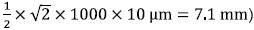
in a microscope with a 200 mm focal length tube lens has a CHA of arctan(7.1/200) = 2.0°.
The effective index can not be adjusted arbitrarily – while there is a small amount of design flexibility, it is strongly constrained
by the choice of materials used for the high- and low-index of refraction thin-film layers of the filter. Figure 6 (left) shows spectra of a green-to-blue VersaChrome filter available from stock in Semrock’s catalog (TBP01-550/15).
The diagram in Figure 6 (right) shows the tuning curve of this filter. The blue curve shows that the center wavelength follows the familiar form of Equation (1) above, and corresponds to an effective index of about
neff = 1.85. The green curve shows that the FWHM bandwidth remains constant at about 20 nm over the entire tuning range. This value of neff is nearly optimal for many applications and is similar for the other
catalog VersaChrome filters.
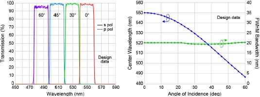
Figure 6: (Left) Transmission spectra at several high angles for both s- and p-polarization for the TBP01-550/15 filter – note the almost nonexistent polarization dependence. (Right) Shift of center wavelength with increasing angle of incidence for this filter; the full-width-at-half-maximum (FWHM) bandwidth remains fixed at 20 nm.
Figure 7 shows spectra from standard catalog VersaChrome filters, illustrating that only five filters are needed to cover the entire visible spectrum.
5. Applications of VersaChrome tunable filters
VersaChrome tunable thin-film filters have widespread potential uses, in areas including: fluorescence microscopy and other fluorescence imaging and quantitation applications, spectral imaging, high-throughput spectroscopy, and telecommunications.
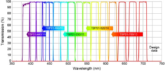
Figure 7: Spectra at 0°, 30°, 45°, and 60° (TBP01-440/16 only) for five Semrock VersaChrome filters available from stock. Each filter is guaranteed to tune over 12% of the normal incidence center wavelength (indicated in the part number) when tuning from 0° to 60°, with the bandwidth remaining fixed at 20 nm over the full tuning range. Only five filters are needed to cover the entire visible wavelength range.
In fluorescence microscopy and other fluorescence measurements, optical filters are critical to control the spectra of the excitation and emission light. Filters make it possible for the sample to “see” only light within the absorption bands of the fluorophores with which it is labeled, and the detector to “see” only light within the emission bands. Without filters, the detector would not be able to distinguish the desired fluorescence from scattered excitation light (especially within the emission band) and autofluorescence from the sample, substrate, and other optics in the system. Achieving maximum measurement speed, highest sensitivity in low-signal experiments, and the best possible signal-to-noise ratio for the clearest contrast and discrimination all require optimal choice of optical filter spectra, especially when trying to distinguish multiple components labeled with distinct yet overlapping fluorophores. Often successful separation of fluorescence emission spectra fails simply due to the fact that the instrument is not equipped with the optimum filters. Tunable filters overcome this problem, while enabling the greatest instrumentation flexibility and even real-time optimization when changing experiments or conditions within a given experiment.
Spectral imaging is used in applications ranging from remote sensing for monitoring of Earth resources to medical imaging, agricultural analysis, forensics, manufacturing, and more. For example, remote sensing analysis has for many years employed spectral imaging to study how sun light is scattered from the Earth’s surface and within the atmosphere. Detailed analysis of the spectral frequencies present in satellite image datasets allows different objects, landscapes, and terrains to be discriminated and characterized. The spectral imaging technique refers to the capture of a series of two-dimensional images, each at a different wavelength, thus resulting in an “image cube” of data in which each volume pixel (or “voxel”) contains an intensity value associated with two spatial dimensions and a wavelength. Commonly spectral imaging is implemented with a “pushbroom” image capture technique, in which a two-dimensional CCD array attached to a grating spectrometer captures individual frames with one-dimensional spatial information along one axis of the CCD and spectral information along the other. The system is then scanned along the other spatial axis (which occurs naturally as an airplane flies over the Earth, for example), so that each successive frame captures a new row of spatial information, displaced in time. However, the availability of high-performance tunable optical filters that transmit a two-dimensional imaging beam makes it possible to implement the often more desirable capture mode in which each frame captures two dimensions of spatial information (which typically benefit from higher resolution requiring more pixels), with the lower-resolution spectral measurements displaced in time.
In recent years, satellite imaging methods based on spectral imaging have been applied by analogy to the investigation of biological samples for spectral karyotyping, resonance energy transfer, colocalization, stained tissue analysis, and the elimination of autofluorescence. In most of these cases, there is simply too much overlap of the emission spectra in multiplelabeling experiments to “see” the labels distinctly. Spectral imaging combined with a class of mathematical algorithms called “linear unmixing” can be used to post-process the direct data and obtain images in which the different components are clearly separated, thus revealing not only the precise locations of biologically relevant targets, but also information about the interactions between them. As the speed and computing power of modern computers increases, this post-processing can even be done in nearly real time.
Tunable optical filters also enable simple, compact spectral measurement systems especially when throughput is more important than spectral resolution. And tunable filters are important elements in fiber-optic telecommunications systems, both for test and measurement purposes and because they have the potential to considerably simplify the complexity of wavelength discrimination components in installed systems by creating “wavelength agility.”
6. Conclusions
VersaChrome has now made possible thin-film bandpass and edge filters that are tunable over a wide range of wavelengths by adjusting the angle of incidence with essentially no change in spectral performance. As a result, many optical systems can now benefit from tunable filters with the spectral and two-dimensional imaging performance characteristics of thin-film filters and the center wavelength tuning speed and flexibility of a diffraction grating.
References
[1] Optical Waves in Layered Media, Pochi Yeh, Wiley, New York, 1988, Section 7.6.
[2] Ibid., Section 10.1.
[3] See, for example, “Tunable thin-film filters: review and perspectives,” M. Lequime, Proc. SPIE,
Vol. 5250, pp. 302-311, 2003 (C. Amra, N. Kaiser, H. A. Macleod, Eds.).
Authors
Turan Erdogan, Ph.D. and Ligang Wang