Spectral Imaging with VersaChrome
1. Introduction
Multicolor fluorescence imaging is ubiquitous in research and clinical applications. When the fluorophores used in such applications have low spectral overlap, standard filter cubes (with fixed spectral edges) are adequate. However, when the crosstalk is high, spectral imaging [1-4] becomes necessary. Spectral imaging systems provide flexibility in wavelength selection. This flexibility is also useful when experiments need to be designed with new fluorophore combinations because optical filters need not be changed in these systems. However, despite their flexibility, conventional spectral imaging systems are rarely able to offer the key advantages of thin-film interference filters, i.e., high transmission combined with steep spectral edges and high out-of-band blocking. This article outlines a novel approach to spectral imaging based on recently introduced tunable thin-film optical filters.
2. Technology
At the heart of this spectral imaging technology is Semrock’s VersaChrome® filters technology. These are the first widely tunable thin-film optical filters [5]. Unlike standard thin-film interference filters, the spectra of VersaChrome® filters can be angle-tuned – the filter spectrum changes as a function of angle of incidence – without exhibiting any appreciable change in the shape of the spectrum.
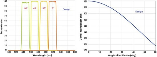
Figure 1: (Left) Transmission spectra at several very high angles for the TBP01-620/15 filter. (Right) Shift of center wavelength with increasing angle of incidence for this filter. The FWHM bandwidth remains fixed at 20 nm (corresponding to 15 nm guaranteed minimum bandwidth). Note that the filter spectrum is continuously tunable over 0 to 60º AOI.
Figure 1 shows snapshots of spectral profiles of one of Semrock’s VersaChrome® filters, TBP01- 620/15, at different angles of incidence (AOI). This filter has a guaranteed minimum bandwidth of 15 nm and a full-width-at-half-maximum bandwidth
of 20 nm. As seen in this figure, the filter not only retains its bandwidth at higher AOIs, but also the high transmission, steep spectral edges, and high out-of-band blocking (not seen in this plot) remain virtually unchanged.
The
center wavelength of this tunable filter (in fact for all VersaChrome® filters) is dictated by the following equation, where neff is the effective refractive index of the thin-film coatings
Here neff is approximately 1.85. Note that the spectrum of this tunable filter is continuously tunable. With a tuning range of greater than 12% of the normal-incidence wavelength (by varying the angle of incidence from 0 to 60º) only five filters are needed to cover the full visible range.
3. Materials and Methods
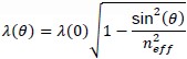
Microscopy: BPAE cells (sample courtesy of Mike Davidson, Molecular Expressions™) labeled with MitoTracker® red (Mitochondria), Alexa Fluor® 568 (F-actin), and SYTOX® Orange (Nucleus) were imaged with an Olympus BX41 microscope equipped with a Hamamatsu ORCA C8484 camera. The emission pathway of this microscope was modified to include a computer-controlled tunable filter module. The principle of operation of this microscope is shown in Figure 2. In order to simultaneously excite all the fluorophores in the sample, a single excitation filter (FF01-543/22-25) and a single-edge dichroic mirror (FF562-Di02-25x36) were installed in a filter cube in the standard filter turret of the microscope. The tunable emission filter, TBP01-620/15-25x36, was placed in the tunable filter module, and a sequence of images were acquired (called a lambda stack of images) by varying the angle of incidence of the filter with respect to the emission beam in 1º increments.
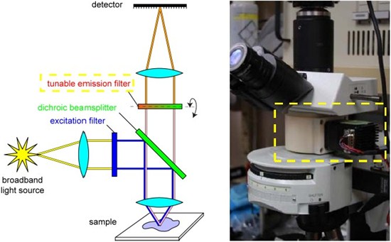
Figure 2: (Left) Principle of operation of the microscope used in this study. (Right) The emission path of a standard Olympus BX41 microscope was modified to include a (stepper) motor controlled tunable filter module. The angle of incidence of the tunable filter (TBP01-620/15-25x36) was adjusted in 1º increments to acquire images of the sample corresponding to different wavelengths. The location of the tunable emission filter is marked with a dotted rectangle.
Linear unmixing:
In order to spectrally deconvolve the data (called linear unmixing, [1-4]), the pixel intensity values were extracted from the lambda stack images and arranged in matrices. MATLAB was used to solve a linear least squares problem of min with
a nonnegativity constraint on x, where x is the matrix of deconvolved spectral contributions from each fluorophore at a given pixel. The matrix A contains the reference fluorophore spectra corresponding to each
of the fluorophores (Figure 4), and the matrix b comprises the intensity values for a given pixel from the lambda stack images.
4. Results
In this study, spectral imaging using tunable filters is illustrated with an example. Lambda stack images of a sample labeled with MitoTracker® red, Alexa Fluor® 568, and SYTOX® Orange were acquired using a Semrock VersaChrome® tunable filter (see Materials and Methods for details). Figure 3 presents images acquired at about 5 nm intervals.
Figure 3: Lambda-stack images of the sample acquired using a tunable emission filter. Images are presented at about 5 nm intervals (refer to Fig.1 for corresponding filter spectra). Cellular components labeled with fluorophores of distinct emission spectra can easily be resolved even in the raw data, however, fluorophores with similar spectra benefit from linear unmixing algorithms. Individual frames represent an object size of about 47µm x 38 µm.
It is evident from these images that the nucleus stained with SYTOX® Orange can be easily discriminated from the other cellular structures – by merely utilizing a single tunable emission filter used to visualize all the fluorophores.
However since F-actin and mitochondria are labeled with fluorophores that have a high degree of spectral overlap (Alexa Fluor® 568 and MitoTracker® red, respectively), linear unmixing was necessary to discern
the corresponding cellular constituents.
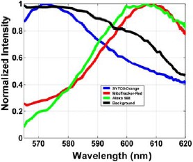
Figure 4: Reference spectra for each fluorophore are plotted as normalized intensity values of the selected regions corresponding to each of the fluorophores in the sample. Note that the measured spectrum of a fluorophore can be different from its ideal spectrum. This can happen due to a change in the environmental conditions or due to limitations in experimental protocols. The background signal is also plotted as a function of the wavelength.
Regions of interest representing the pure spectral contribution of each fluorophore were selected from the lambda-stack images shown in Figure 3. The normalized intensity values (following background adjustment) corresponding to each of these fluorophores are plotted in Figure 4. These represent the reference spectra of the fluorophores used in the unmixing algorithm. The lambda-stack images were then used together with a linear unmixing algorithm (see Materials and Methods) to arrive at spectrally deconvolved images for all the fluorophores (Figure 5).
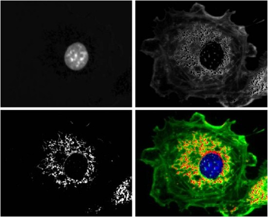
Figure 5: Spectrally unmixed data. The grayscale images correspond to cellular components labeled with specific fluorophores: nucleus (top left), F-actin (top right) and Mitochondria (bottom left). Bottom right is a composite image. Individual frames represent an object size of about 47µm x 38 µm.
5. Conclusions
VersaChrome® filters can be placed in the excitation or emission path of a fluorescence instrument and by merely changing the angle of incidence of the filter with respect to the beam, different spectral features can be obtained. Also, it is worth pointing out that the spectral properties of these tunable filters are almost identical for both s and p polarizations of light – a feature that cannot be easily obtained using liquid-crystal and acousto-optic tunable filters [2-5]. Polarization independence is highly desirable for spectral imaging systems, and yet polarization limitations of current tunable filters can account for a loss of half of the signal in many spectral scanning instruments. VersaChrome ® filters, on the other hand, do not exhibit such a loss of signal. Therefore these filters can not only enhance the throughput in spectral imaging but they can also greatly simplify the complexity of instrumentation [5].
References
[1] Visualization of Microscopy-Based Spectral Imaging Data from Multi-Label Tissue Sections, Mansfield JR, Hoyt C, Richard, RM, Current Protocols in Molecular Biology, 84:14.19.1-14.19.15 2008.
[2] Spectral Imaging: Principles and Applications.
Garini Y, Young IT, McNamara G., Cytometry A, 69(8):735-47, 2006.
[3] Multispectral Imaging Fluorescence Microscopy for Living Cells, Hiraoka Y, Shimi T., and Haraguchi T. Cell Structure and Function, 27: 367-374, 2002.
[4] http://zeiss-campus.magnet.fsu.edu/
[5] Semrock VersaChrome ™ – the First Widely Tunable Thin-film Optical Filters, Erdogan T and Wang
L, 2010.
Authors
Prashant Prabhat, Ph.D., Neil Anderson, Ph.D., and Turan Erdogan, Ph.D.
Acknowledgements
The authors would like to acknowledge the support of Professor Mike Davidson, at Florida State University, for this study.