Ion-Beam-Sputtered (IBS) Thin-film Interference Filters for Nonlinear Optical Imaging
Abstract
Nonlinear optical (NLO) microscopy is emerging as a powerful technique for the study of biological samples. By combining several different imaging modalities such as multiphoton (MP) fluorescence, second-harmonic and third-harmonic generation (SHG and THG), and coherent Raman scattering techniques such as coherent anti-Stokes Raman scattering (CARS) and stimulated Raman scattering (SRS), it is possible to combine the best practices of label and label-free imaging into a single platform capable f imaging structures within single cells and elucidating the health of biological tissue samples, even at the submicron level. Single-substrate, ion-beam-sputtered (IBS) thin-film interference filters are a key enabling technology in laser-based optical microscopy and play a critical role in multimodal NLO imaging. In microscopy applications, optical filters are used to select and discriminate exactly which wavelengths of light are to be transmitted, reflected and suppressed. In this paper we discuss various important characteristics of hard-coated thin-film interference filters, such as high light throughput, steep edges, and high out-of-band blocking, all of which require careful consideration when designing and manufacturing optical filters for NLO imaging applications. To understand the true performance of hard-coated IBS filters, a simple CARS imaging experiment was performed. We found a 2.6 times increase in signal enhancement and 70% improvement in image contrast when compared to a commercially available filter commonly used in CARS microscopy applications.
1. Introduction
Nonlinear optical (NLO) microscopy is emerging as a highly valuable imaging tool for basic life science research and biomedical applications. It can be used to image structures within and around individual cells, and probe the disease state of tissue samples. Nonlinear optical microscopy exploits several well-known nonlinear optical processes in order to produce high contrast, chemically specific images. The most common NLO imaging modalities are: multiphoton (MP) fluorescence; second- and third-harmonic generation (SHG and THG); and coherent Raman scattering (CRS). In MP fluorescence microscopy a single femtosecond laser is used to excite the sample to emit fluorescence via a multiphoton process. In two-photon (2P) fluorescence microscopy two incident photons are used to generate one emitted fluorescence photon. In three-photon (3P) fluorescence microscopy three incident photons are used to generate one emitted fluorescence photon. Two-photon fluorescence imaging is commonly used in conjunction with fluorescent markers such as fluorescent proteins and organic dyes. This approach can also be used to generate contrast by exciting sample autofluorescence [1]. Three-photon (3P) fluorescence imaging is commonly used with endogenous fluorophores such as collagen or tryptophan, which provide structural information in many different types of tissue sample without the need for external fluorescent labels [1].
Additional label-free imaging can be achieved by exploiting intrinsic second- and third-harmonic nonlinear optical effects within biological samples. Second-harmonic generation is an energy-conserving process in which two incident photons at optical frequency wi interact at the sample to create a single emission photon having twice the energy, i.e., wSHG = 2wi, (where w is the optical frequency equal to 2pc/λ, with c the speed of light in vacuum and λ the wavelength). A prerequisite for SHG microscopy is that the sample must exhibit a significant degree of noncentrosymmetric order at the molecular level. SHG microscopy is commonly used to spatially map cell boundaries and collagen [3].
Third-harmonic generation is also an energy conserving process in which three incident photons are involved in the generation of one emission photon, i.e., wTHG = 3wi. THG microscopy can also be used to image cell boundaries at the sub-micron level [4].
All of the aforementioned nonlinear optical imaging techniques utilize the high peak powers available from a single femtosecond laser operating in the near-infrared (NIR) wavelength range. Coherent Raman scattering (CRS) microscopy on the other hand, requires the use of two synchronized picosecond laser sources to generate appreciable image contrast. Two distinct CRS microscopy approaches exist: coherent anti-Stokes Raman scattering (CARS) and stimulated Raman scattering (SRS). In the CARS process, a pump laser beam (at optical frequency wpump) and a Stokes laser beam (at wStokes) interact at the sample to produce an anti-Stokes Raman signal at the optical frequency wCARS = wpump – wStrokes. When the frequency difference between the pump and the Stokes lasers matches the frequency of a vibrational mode (W), the molecular oscillators are coherently driven. The result is an enhanced anti-Stokes (shorter-wavelength) Raman signal that is the basis for the increased vibrational contrast in CARS microscopy [5]. In SRS microscopy, both the pump and Stokes beams are incident on the sample, as in CARS, but in SRS only a single pump and a single Stokes photon interact at the sample. If the frequency difference wSRS=wpump – wStrokes matches a molecular vibration (W), stimulated excitation of the vibrational transition occurs resulting in stimulated gain and loss of the Stokes and pump beams, respectively [6]. An example of how all of the aforementioned NLO imaging modalities can be brought together in a single, multimodal NLO microscopy platform is shown in Figure 1 below.
Common to all nonlinear optical imaging modalities is the need for high peak-power lasers to generate and drive the various nonlinear processes within the sample, in addition to high-sensitivity detectors. A third enabling technology crucial to all NLO imaging systems are high-performance, hard-coated optical filters. Optical filters are used to precisely control and manage the various different light signals over a range of well-defined and specific spectral bands in both the excitation and detection arms of a NLO imaging microscope. In this article, we discuss the design and manufacture of single-substrate, ion-beam-sputtered (IBS) dichroic and emission filters for use in nonlinear optical imaging applications. The enhanced imaging performance provided by IBS coated optical filters is demonstrated by comparing image data obtained from a CARS microscopy experiment.
2. IBS Coated Optical Filters for Nonlinear Optical Imaging
2.1 Ion-beam-sputtered (IBS) filters for multiphoton (MP) fluorescence and harmonic generation imaging
In 2P, 3P, SHG and THG microscopy high signal-to-noise ratio (SNR) imaging is paramount, especially if quantitative data is required to enable accurate disease diagnosis. To enable high contrast NLO imaging it is important to carefully select the right dichroic beamsplitter and the right emission filter. The role of a dichroic beamsplitter is to direct the incident laser light via transmission (or reflection) towards the sample, while directing the emitted fluorescence to the detector channel via reflection (or transmission). The role of an emission filter is to transmit as much of the desired fluorescence or harmonic signal as possible while blocking all other light signals. To achieve the best performance the dichroic beamsplitters and emission filters should be designed as matched pairs. Two examples of matched dichroic-emitter pairs for (long-wavelength) multiphoton imaging are shown in Figure 2.
The key characteristics of a matched dichroic-emitter pair are described as follows. Most two-photon (2P) microscopes are equipped with a femtosecond (fs) Ti:sapphire laser, which can be wavelength tuned across a range as wide as 650-1100 nm. Therefore, the dichroic beamsplitter should provide high transmission (typically > 95%) over this range of wavelengths. New laser sources that extend the tuning range in the NIR from 650-1300 nm are commercially available and as such, it is necessary to design new dichroic beamsplitters that enable longer wavelength multiphoton imaging using these sources. With this in mind, extended high transmission out to 1400 nm and beyond has been designed into the two dichroics (FF775-Di01 and FF875-Di01) shown in Figure 2 (top). In addition, both dichroics exhibit high reflectivity (typically > 98%) down to 350 nm. Steep transition edges, on the order of < 30 nm, are built into the design of all matched dichroic-emitter pairs, enabling users to collect as much longer wavelength fluorescence as possible. The dichroic filters shown in Figure 2 were designed for use in a multiphoton microscope configured in a transmission geometry. Dispersion compensated dichroic beamsplitters for reflection-mode multiphoton imaging experiments are also available [7].
As mentioned previously, precise spectral control over the emitted fluorescence is readily achieved by using an emission filter designed to work in unison with the dichroic beamsplitter. For optimum imaging performance, emission filters are designed to provide high transmission (typically > 95%) across the range of wavelengths where the fluorescence emission occurs. Shown in Figure 2 are two emission filters (FF01-790/SP and FF01-890/SP, both green) designed to transmit light from the near-UV to the near-IR, and both filters are ideally suited for 2P, 3P, SHG and THG imaging applications. Traditionally, all multiphoton emission filters were required to have very high blocking over the Ti:sapphire wavelength tuning range. However, Semrock pioneered a more cost-effective solution by recommending that two emission filters be placed in the detection arm of the microscope, (see Figure 1). The first emission filter is a short-wave-pass (SWP) filter, such as a FF01-790/SP or FF01-890/SP, which provides extended blocking over a wide wavelength range in the near-infrared (NIR) (see Figure 2). It is recommended that such a laser blocking filter be positioned in the emission path for all multiphoton and harmonic generation microscopy experiments. A second emission filter, which could be a standard hard-coated fluorescence bandpass filter without high extended blocking across the full Ti:Sapphire wavelength range, can then be placed in the emission path with the sole purpose of transmitting the desired range of fluorescence emission from the fluorophore of interest.
Furthermore, since high peak-power femtosecond lasers are used, it is necessary to design emission filters that provide blocking at optical density (OD) 6 or higher outside the defined passband. This has been achieved previously through the use of multiple substrates, with each substrate having specific coatings to provide adequate blocking. However, the use of multiple-substrate designs is not ideal and can be problematic. Since two or more individual substrates are used and each surface has a coating that performs one specific function (i.e., to transmit a specific wavelength range or to provide additional blocking), any error in the manufacturing process of the four independent coatings can lead to misplaced passband edges and can result in the passage of unwanted background signals and stray light. Greater than OD 6 level out-of-band blocking over a broad spectral range from a single substrate design is possible, as is clearly demonstrated by inspection of the blocking profiles of two emission filters designed specifically for multiphoton imaging applications shown in Figure 2 (bottom). To mitigate any such issues all of Semrock’s hard-coated optical filters are based on a single-substrate design.
Figure 2. Linear transmission plots (top) of the spectral characteristics of two matched dichroic (red line) – emitter (green line) pairs for long wavelength multiphoton imaging. The optical density (OD) plots (bottom) reveal the out-of-band blocking performance of both emission filters. As indicated by the blue dashed lines, greater than OD 6 blocking is provided out to 1400 nm.
2.2 Ion-beam sputtered (IBS) filters for coherent Raman scattering (CRS) imaging
In coherent Raman scattering (CRS) microscopy, two independent picosecond lasers are used. Longer pulses are preferred due to the narrower spectral width of the laser line, which provides a more precise match to the Raman spectral features. In order to generate appreciable CRS signals these two laser beams must be spatially (and temporally) overlapped prior to entering the microscope head. To help achieve this condition, a single notch dichroic beamsplitter designed to work at 45o can be used. An example of how such a filter is configured in a CRS microscope experiment is shown in Figure 1. In this example, the notch dichroic filter allows a Stokes beam fixed at 1064 nm to be directed towards the microscope via reflection, while the pump laser beam (700-1100 nm) is transmitted. The spectral profile of such a filter is shown in Figure 3 (left, blue). The main features of the notch dichroic are greater than 95% transmission across the wavelength tuning range of the pump laser, with a narrow reflection band centered at 1064 nm. Extended high transmission across the wavelength range 400-1000 nm and 1150-1400 nm makes this filter ideally suited to imaging applications where CARS or SRS imaging is combined with other NLO imaging modalities, such as 2P fluorescence or SHG and THG imaging.
Ion-beam sputtered, hard-coated emission filters are also ideal for wavelength selection in CARS and SRS microscopy where achieving high image contrast is a must. The spectral performance requirements of emission filters used in CARS and SRS microscopy are similar to those for MP fluorescence imaging, namely, greater than 95% transmission across the passband and greater than OD 6 out-of-band blocking outside the defined passband. Linear transmission plots of two emission filters designed for CARS (green) and SRS (red) microscopy are shown in Figure 3 (left). For CARS imaging, it is conceivable to use a wideband multiphoton emission filter. The use of such an emission filter would however also transmit the broad nonresonant background generated in the CARS process and lead to a loss of image contrast. A dedicated emission filter for CARS imaging is required. An example of one such filter that can be used to capture the anti-Stokes Raman scattered light associated with, for example the CH2 stretching vibration is the FF01-625/90 filter shown in Figure 3 (left). The CARS emission filter shown can also be used to detect the 2P fluorescence emission from various different orange and red fluorescent proteins.
Similar requirements govern the need to collect the Raman signal in SRS microscopy. In addition to providing high transmission across the entire tuning range of the pump source, typically 700-1000 nm, efficient blocking of the Stokes laser at 1064 nm is also provided. The linear transmission profile of an emission filter (FF01-850/310) designed specifically for SRS imaging (red) is also shown in Figure 3 (left). The out-of-band blocking profiles for both CARS and SRS emission filters discussed above are shown in Figure 3 (right). Both emission filters provide greater than OD 6 blocking from 1025-1400 nm, with OD 8 blocking built into the design of each filter at 1064 nm.
Figure 3. Linear transmission (left) and optical density (OD) (right) plots of three filters that enable high image contrast coherent Raman scattering (CRS) microscopy. A single notch dichroic beamsplitter designed for 45o (blue) can be used to efficiently direct the pump (700-1000 nm) and Stokes (1064 nm) lasers towards the microscope. The spectral profiles of two bandpass filters suitable for the detection of CARS (green) and SRS (red) Raman signals respectively are also shown.
3. Manufacturing IBS Coated Optical Filters
3.1 Manufacturing techniques for thin-film interference filters
Delivering optimum imaging performance through careful and thoughtful filter design is paramount for nonlinear optical microscopy applications, where many different light signals are to be detected. Just as important is a need to fully understand the various options available with which to reliably and repeatedly manufacture thin-film optical filters that exceed the requirements of these imaging applications. In this section we present a description of the common deposition processes used in the manufacture of thin-film optical filters and discuss the merits of each.
Two common methods used to deposit thin-film coatings are centered around evaporation and sputtering. Evaporated coatings are formed at low energy (~ 1 eV). As a result the packing density is low and defects, such as microcrystals and pinholes, can form in the coating structure. Environmental contaminants are also a problem. Water vapor, for example, can diffuse into the multilayer stack of an evaporated coating and shift of the center wavelength of the transmission band away from the theoretical design and impact the true imaging performance of the filter. Therefore, evaporated coatings have limitations in demanding research, where the collection of repeatable scientific data over an extended period of time is critical. To overcome the inherent drawbacks of evaporated coatings, deposition techniques such as magnetron and ion-beam sputtering (IBS) are preferred. In the sputtering process material ions are deposited at high energy (~ 10 eV). This results in the deposition of densely packed layers, and hence coatings, that are chemically inert and mechanically stable under a wide variety of environmental conditions. Another important aspect that differentiates sputtering from evaporated techniques is the ability to precisely monitor and control the thickness of each individual layer throughout the entire deposition process from start to finish. The net result is multilayer coatings with spectral performance characteristics that match initial theoretical design. In comparing sputtering techniques, IBS deposition can be used to deposit very high (> 200) layer count coatings that exhibit high laser damage threshold (LDT) values in excess of 20 J/cm2. Furthermore, due to the close proximity between the target and glass substrate in a magnetron chamber, increased numbers of surface defects, such as pinholes, are formed in the coating. Pinholes typically result in the passage of increased levels of stray light into the detection arm of the microscope and can lead to a reduction in overall image contrast. Because of the greater separation between the ion source, target and substrate, pinhole formation in IBS coated optical filters can be more readily controlled. As such, IBS is the preferred choice for manufacturing single-substrate optical filters for nonlinear imaging and other photon sensitive experiments. A comparison between evaporation and sputtering techniques is presented in Table 1.
| Electron Beam Evaporation | Magnetron Sputtering | Ion Beam Sputtering | |
| Number of layers | < 100 | > 100 | > 200 |
| Average transmission (%) | < 95 | > 95 | > 95 |
| LDT (J/cm2)1 | 5 to 30 | ~ 10 | > 50 |
| Density | Porous | Dense | Dense |
| Average # pinholes2 | Few | Very few | Very few |
1Measured using 1064nm, 20 ns pulsed laser light. 2Measured from 25 mm diameter parts.
The superior deposition capabilities offered by ion-beam-sputtering are readily apparent based on a comparison of the theoretical design and measured spectral characteristics of a manufactured part. An example of this is shown in Figure 4, where the theoretical design of a CARS emission filter (FF01-625/90) is compared with the spectral profile measured from a manufactured filter. Inspection of Figure 4 (left) clearly reveals the near-identical spectral overlap between the two plots. Here, the average transmission across the pass band was measured ~97%. The accuracy with which the IBS process was able to locate the edge position is extremely good, as the plots in Figure 4 show. Furthermore, Figure 4 (right) reveals that the out-of-band blocking was measured at greater than OD6 across the wavelength range 800-1100 nm, highlighting the ability of this filter to suppress stray excitation light during CARS imaging.
Figure 4. Linear transmission (left) and optical density (OD) (right) plots of the theoretical design (red) and measured (green) spectrum from the CARS emission filter FF01-625/90. As indicated by the blue dashed line, greater than OD6 out-of-band blocking extends to 1100 nm. Note that the disagreement between the theoretical and measured spectra from high OD (>6) is mainly due to artifacts of the measurement method used [8].
4. Coherent Anti-Strokes Raman Scattering Imaging Using IBS Coated Optical Filters
4.1 Coherent anti-Stokes Raman scattering (CARS) imaging with IBS coated optical filters
The implementation and use of any optical filter in a real-world imaging experiment is the ultimate test of its performance. In order to elucidate the true imaging performance of the Semrock filter FF01-625/90, a CARS imaging experiment was performed. A sample of cholesteryl palmitate was prepared on a clean glass microscope cover glass. To enable direct imaging of the spatial distribution of CH2 molecules from within the sample the pump and Stokes lasers were set such that the following condition was met,wCARS = 2wpump - wStokes = 2845 cm-1. The resultant images acquired in this experiment are shown in Figure 5. One CARS image was acquired using a FF01-625/90 filter (left). A second CARS image was also acquired. Here, the FF01-625/90 emission filter was replaced with a commercially available bandpass filter (650/40) commonly used in CARS imaging applications. A CARS image of the same region of interest (ROI) was subsequently acquired and is shown in Figure 5 (right). The laser power and detector settings were kept constant throughout both experiments.
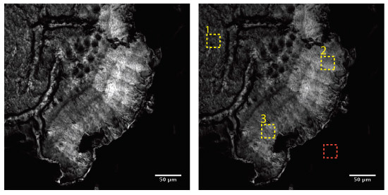
To understand the advantages of IBS coated filters for CARS imaging, a quantitative assessment was performed using the image data displayed in Figure 5. In order to obtain the quantitative values as listed in Table 2, the mean signal intensity <S> was calculated from three spatially distinct regions of interest (ROI), as shown in Figure 5. Each separate ROI is indicated by the yellow dashed boxes. The mean background intensity <B> was calculated from a separate ROI, indicated by the red dashed box. The signal-to-noise ratio (SNR) was then computed using the following equation:
 (1)
(1)
where <sB> denotes the standard deviation of the background. The values of <S>, <B>, <sB> obtained from the image data are presented in Table 2, along with the calculated values of the SNR for each of the three ROI’s. The normalized SNR and signal <S> are also tabulated.
Based on this imaging experiment, we found that the FF01-625/90 filter provided greater than 2.6 times higher CARS signal. Furthermore, the overall image contrast (SNR) was found to be ~70% better when compared to the contrast obtained with the other commercially available bandpass filter commonly used in CARS imaging. In terms of design and manufacturing of this filter, we attribute as key factors the high blocking specification of the FF01-625/90 filter as well as optimized SWP and LWP edge locations of the passband, both of which ensure maximum signal collection efficiency in the spectral region of interest.
| ROI-1 | ROI-2 | ROI-3 | |||||
| 650/40 | FF01-625/90 | 650/40 | FF01-625/90 | 650/40 | FF01-625/90 | ||
| Signal | Mean <S> | 801 | 2099 | 597 | 1547 | 392 | 1033 |
Std Dev <ss> | 202 | 556 | 152 | 411 | 120 | 354 | |
| Background | Mean <B> | 61 | 64 | 61 | 64 | 61 | 64 |
| Std Dev sB | 3 | 5 | 3 | 5 | 3 | 5 | |
| Signal-to-noise ratio (SNR) | 247 | 407 | 179 | 297 | 110 | 194 | |
| Signal-to-noise (normalized) | 100% | 165% | 100% | 166% | 100% | 176% | |
| Signal (Normalized) | 100% | 262% | 100% | 259% | 100% | 364% | |
References
[1] Zipfel, W.R. et al., “Nonlinear magic: multiphoton microscopy in the biosciences”, Nat Biotech, 21(11), 1369-1377 (2003).
[2] Zipfel, W.R., et al., “Live tissue intrinsic emission microscopy using multiphoton excited native fluorescence and second-harmonic generation”, PNAS, 100(12), 7075-7080 (2003).
[3] Pfeffer, C.P. et al., “Multimodal nonlinear optical imaging of collagen arrays”, J Struct Biol, 164 (1), 140-145 (2008).
[4] Farrar, M.J. et al., “In vivo imaging of myelin in the vertebrate central nervous system using third harmonic generation microscopy”, Biophys J, 100 (8), 1362-1371 (2011).
[5] Evans, C.L. and Xie, X.S., “Coherent anti-Stokes Raman scattering microscopy: chemical imaging for biology and medicine, Ann Rev of Analyt Chem, 1(1), 883-909 (2008).
[6] Freudiger, C.W. et al., “Label-free biomedical imaging with high sensitivity by stimulated Raman scattering microscopy, Science, 322, 1857-1861 (2008).
[7] Anderson, N. and Erdogan, T., Multimodal NLO Imaging, IDEX Health & Science | Semrock
[8] Prabhat, P. and Erdogan, T., Measurement of Optical Filter Spectra, IDEX Health & Science | Semrock
Acknowledgements
The authors would like to acknowledge the support of Professor Eric O. Potma, at University of California, Irvine in performing the CARS imaging experiments.
Author Details
Neil Anderson, Ph.D., Prashant Prabhat, Ph.D., and Turan Erdogan Ph.D.