Injectors Troubleshooting Guide
Our troubleshooting guide provides solutions to common problems encountered when operating our manual sample injection valves. Each problem/symptom is described and is followed by a detailed discussion of potential causes and solutions.
This information is a compilation of 25 years of technical expertise and experience with sample injection and fluidic technology.
Use the links below to jump to different sections:
- How to Use this Guide
- Leaks
- Artifact Peaks
- Non-Reproducible Results
- Decreased System Pressure
- Blockage — High Back Pressure
- Noise or Drift
- Appendices
How to Use This Guide
This Troubleshooting Guide discusses IDEX Health & Science Models 7125, 7126, 7725, 8125, 8126, 9725, and 9726. The Exploded View of Injectors shows the internal parts of a generic injector. Appendix A shows specific models.
Inside Injectors
High pressure switching and sealing takes place between a ceramic stator face assembly and a polymeric rotor seal. The rotor seal wears with use and usually is the only part that may need replacement. In normal use it will last many thousands of injections. IDEX Health & Science RheBuild™ Kits are available for all injectors. Kits contain only genuine IDEX Health & Science parts together with tools and instructions.
The “Comments” section at the bottom of each subject has useful supplemental information.
ChromTrac and RheFlex Fittings, and Sample Loops
IDEX Health & Science established color-code standards for valve fittings as a convenient means to visually identify and trace tubing connections. The illustration below shows brightly colored ChromTRAC™ knobs. To order, contact an authorized Distributor.
Tips on Using Injectors
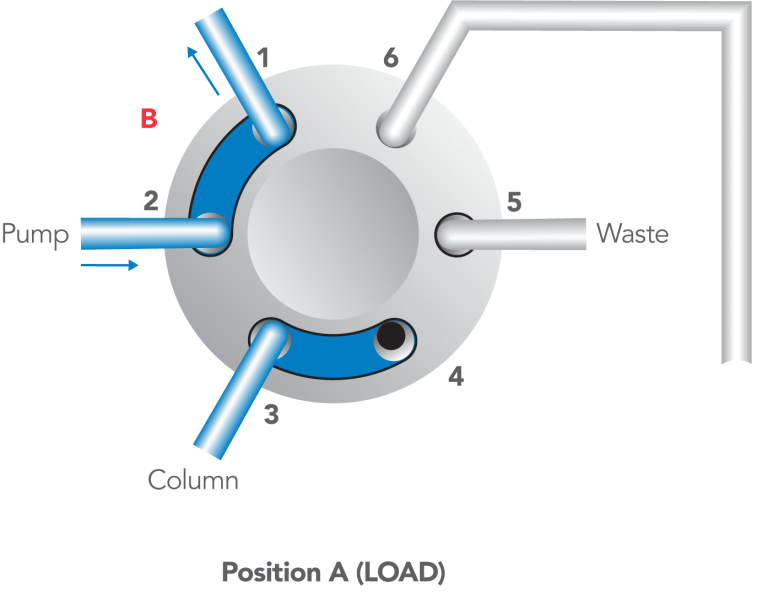
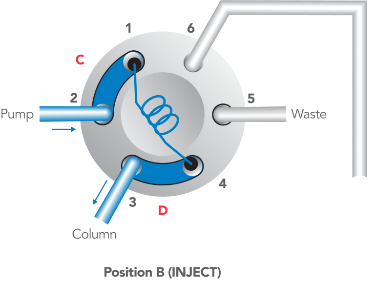
The Model 7125, 7725, and other front-loading models can use both the partial-filling method and the complete-filling method of loading the loop. These are discussed in Appendix F. Following is a summary of procedures.
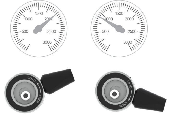
- Steps to inject a sample:
- With the handle on LOAD, insert the syringe into the needle port until it stops.
- Dispense the sample; turn the handle rapidly to INJECT.
- Remove the syringe.
- Wait until you are ready to run the next sample, then return to LOAD.
- Flush in the INJECT position, not in LOAD.>
After turning to INJECT, it is OK to remove the syringe, but keep the handle in this position so the loop is continually flushed with mobile phase.
Manual flushing of the needle port after every injection to prevent cross contamination is rarely necessary. A patented direct-connection port design connects the tip of the syringe needle directly to the end of the sample loop; there is no connecting passage that traps sample, which can enter the loop when the next sample is loaded.
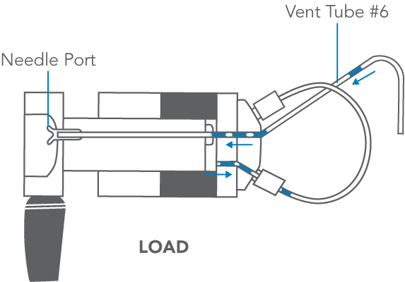
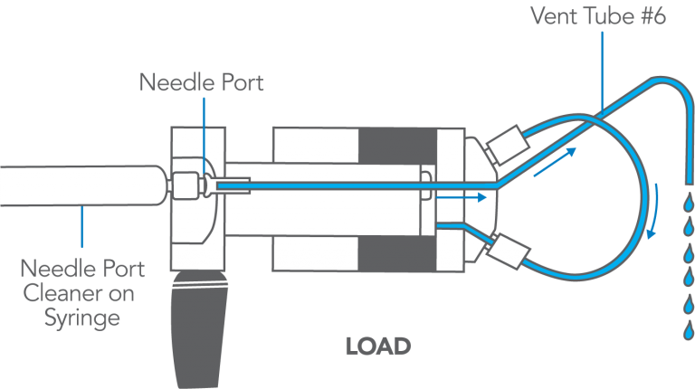
It is good practice to flush the needle port after every ten or twenty injections. This keeps it filled with liquid, which baths the syringe needle and dilutes any sample that contaminates this region during movement of the syringe into or out of the port. It also keeps the needle port and vent tube #5 filled with solvent, preventing air from inadvertently entering the loop. To flush, use from 0.1 to 1 mL of mobile phase. Do it while still in the INJECT position so flow goes directly out vent tube #5 and bypasses the loop that has already been flushed by the pump. Appendix E has more information.
- Flush using the Needle Port Cleaner, not a needle.
Use the Needle Port Cleaner (a small PTFE part without a needle attached), IDEX Health & Science part number 7125-054, attached to a luer tip syringe. This flushes the entire length of the port. A fully inserted needle flushes none of it.
- Do not load a sample volume equal to the loop volume.
You will lose up to 20% of sample out the vent tube, producing poor accuracy and precision. Load <50% of the loop volume (partial-filling) or >200% (complete-filling).
- A 20 µL sample loop does not contain 20 µL.
The size designations of loops are nominal. Actual volumes differ because of the tolerance of the tubing bore. Tubes are cut to length and not volumetrically calibrated. Accuracy of large loops (2 mL) is about 5%, intermediate loops (20 µL) 10%, and small loops (5 µL) 30%. Although complete-filling provides the best precision (reproducibility), use partial-filling if you must know with accuracy the actual volume injected.
- Keep vent tubes and needle port at the same level.
Adjust the end of the vent tubes to the same height as the needle port so liquid does not siphon out. Siphoning sucks air into the loop. Liquid left inside the needle port will bathe the syringe needle as it enters, preventing traces of sample from depositing on the wall of the port.
- Use the proper syringe needle.
The needle should be #22 gauge 0.7 mm (5 cm, 2 in) OD, 5.1 cm (2 in) long, with a 90° point (square end) and no electrotaper. Model 3725 requires a #16 gauge needle.
Exploded View of Injectors
The drawing to the right shows the internal parts of a generic IDEX Health & Science front-loading injector. See Appendix A for drawings and part numbers for specific models: 7125, 7725, etc.
Do not disassemble the injector unless instructed to do so in one of the Solutions. To disassemble:
- If you removed the injector from a panel, replace the knob before proceeding.
- Remove the three stator screws.
- Remove the stator, stator face assembly (this may remain attached to the stator), and stator ring from the valve body by pulling axially to disengage the parts.
- Lift the rotor seal off the seal pins using a knife blade. Leave the isolation seal and bearing ring in place.
In the case of the models with a pressure-adjusting screw, before reassembling loosen the pressure adjusting screw about 1/2 turn before tightening the stator screws. Then retighten the pressure adjusting screw.
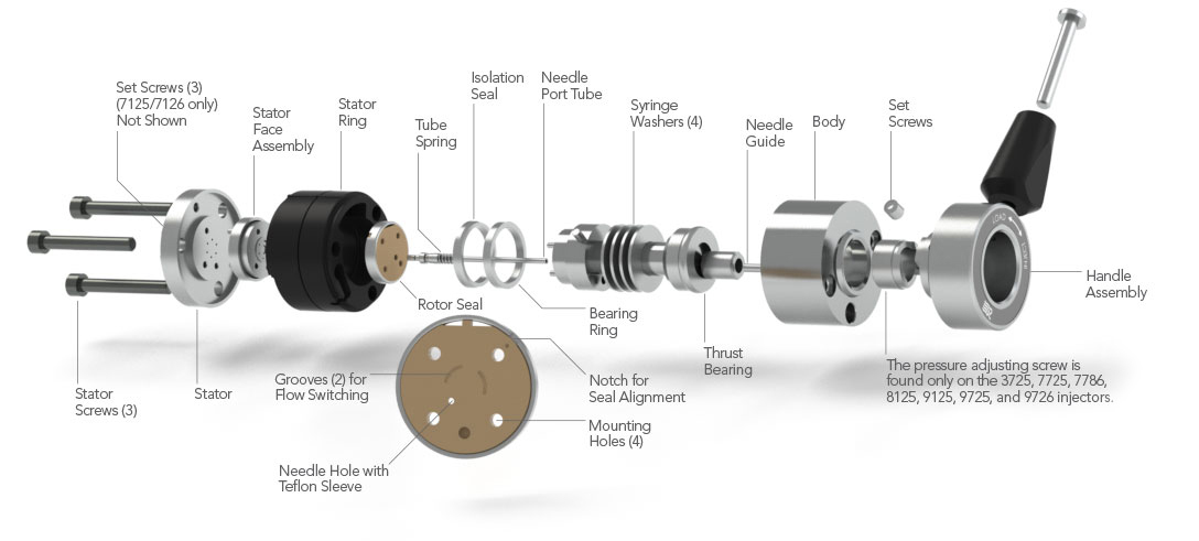
Note: The stator set screws are only found on the 7125 injector. The pressure adjusting screw is only found on the 7725, 7726, 8125, 8126, 9725, 9726, and 3725 injectors
Leaks
Leaks can appear at three locations in the injector: 1) needle port, 2) vent tubes, or 3) the gap between the stator and stator ring.
A leak can be caused by a damaged rotor seal, but there are many leak problems that do not require seal replacement. In the latter case a simple adjustment of the injector, without disassembly, can fix the leak. Read Symptoms 1, 2, and 3 before taking action.
Figure 2: Leak points on an injector
COMMENTS:
The most common cause of early rotor seal failure is surface scratches caused by abrasive particles. These particles can be debris from the sample, mobile phase, or salt crystals from buffer solutions. In the case of metal injectors, particles or burrs from the tubing or fittings can also cause scratching.
In some orientations of the injector, a leak between the stator and stator ring will appear as though the leak is at a fitting in the stator. Likewise, a leak at a fitting may appear as though the leak is between the stator and stator ring. Confirm the true source of the leak before making adjustments.
The following practices provide maximum rotor seal lifetime:
- Check all tubing for burrs and flush it before connecting to the system.
- Filter particles from the mobile phase and filter samples if they are not clean.
- Install a filter between the pump and injector to protect the injector from particles from the pump or mobile phase.
- Frequently flush the injector with water when using buffers, especially before shutting down.
Symptom 1: Leaks at needle port — only while loading
Symptom 1: Fluid leaks out the needle port only while loading the loop; i.e., while depressing the plunger of the syringe (see Figure 3).
Slowly insert the syringe needle all the way into the needle port and notice the friction:
- If friction increases slightly during the last 3 mm of travel and the needle then comes to a hard stop, see Cause A.
- If the friction does not increase, the needle does not penetrate the needle port as far as previously and the stop seems somewhat soft, see Cause B.
Cause A
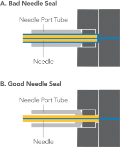
The needle is penetrating the needle seal (see Figure 4), but the seal is not gripping tightly enough to prevent leakage around the needle. Some or all of the sample flows back into the needle port tube and out the needle port. See Comments.
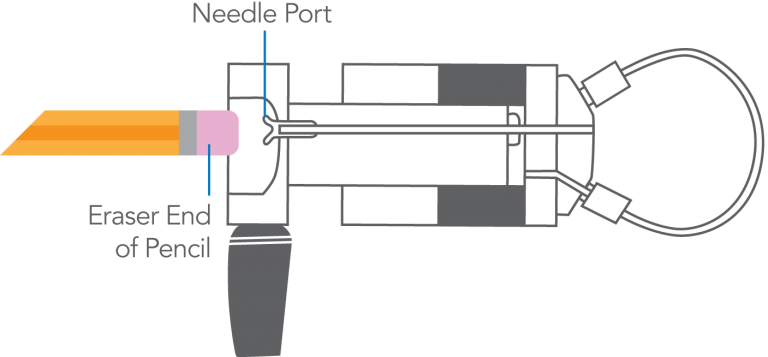
Solution: Push in on the plastic needle guide with the eraser tip of a pencil (see Figure 5). This pushes on the needle port tube, which compresses the needle seal, reducing the hole diameter.
Cause B
The needle is not penetrating through the hole in the needle seal. The diameter of the hole has decreased due to cold flow of the Teflon®. Most or all of the sample flows back into the needle port tube and out the needle port.
Solution: Remove the rotor seal from the injector, and use the needle of your syringe (22# gauge) to increase the diameter of the hole by pushing the needle through it. Important: Do not do this with a Model 3725. Replace the rotor seal if the needle seal is damaged beyond repair (see Comments).
Figure 3. Sample leaking out the needle port while loading sample.
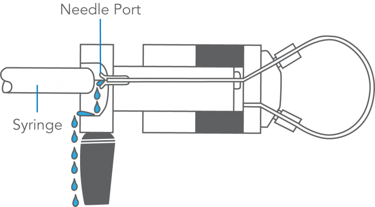
Figure 4. Detailed view of the needle seal (located in the rotor seal) sealing around needle.
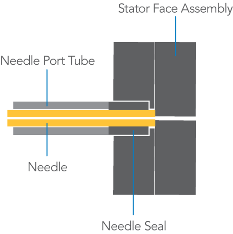
Figure 5. To reform the needle seal, push the eraser end of a pencil against the needle port.
COMMENTS:
When the syringe is inserted, the needle travels along the needle port tube for about 4.5 cm before it reaches the needle seal. During this time the friction is low. Then the tip of the needle enters the needle seal and travels another 3 mm, during which time the friction is higher. The needle is stopped by contact with the ceramic stator face.
Failure of the needle seal is more likely when vent tube #6 is plugged by buffer salt crystals. Check that tube if you suspect Cause A.
Leakage out the needle port will occur when using the wrong syringe. When the needle is too short, the tip will not reach the needle seal. When the needle is too small in diameter, the seal will not grip it tightly enough. The needle should be 0.7 mm OD (#22 gauge) x 5.1 cm (2 in) long and 90° point style (square-cut end). The Model 3725 requires a .062 – .065 mm OD needle x 5.1 cm (2 in).
Do not use a beveled, pointed, or tapered needle.
It is normal for fluid to pass from the port as the needle is inserted. It displaces fluid left in the port after flushing.
Leakage out the needle port during loading will cause non-reproducible analytical results. See Symptom 7.
IIDEX Health & Science RheBuild™ Kits are available for all injectors. Kits contain only genuine IDEX Health & Science parts together with tools and instructions.
Symptom 2: Leaks at needle port or vents — but stops
Symptom 2: Fluid leaks out the needle port or vent tube(s), but eventually stops (see Figure 6).
Slowly insert the syringe needle all the way into the needle port and notice the friction:
- If the fluid leaks out the vent tube(s), see Cause A.
- If the fluid leaks out the needle port, see Cause B.
Cause A
The vent tube(s) is lower than the needle port, which causes fluid to siphon out (see Figure 7).
Solution: Adjust the vent tube(s) so that its outlet is at the same horizontal level as the needle port.
Cause B
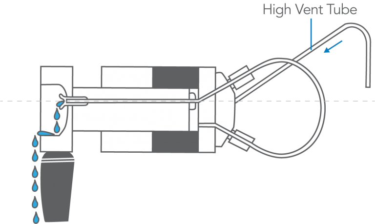
The vent tube(s) is higher than the needle port, which causes fluid to siphon out (see Figure 8).
Solution: Adjust the vent tube(s) so that its outlet is at the same horizontal level as the needle port.
Figure 6: Leaks out vent tube and needle port.
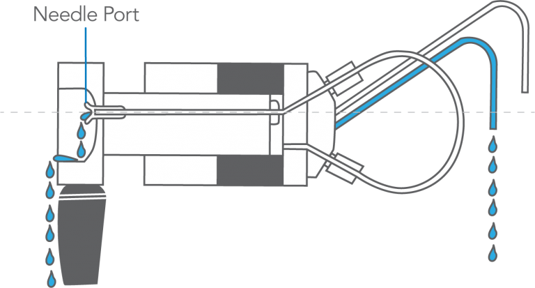
Figure 7: Vent tube low relative to needle port can cause siphoning out the vent tube.
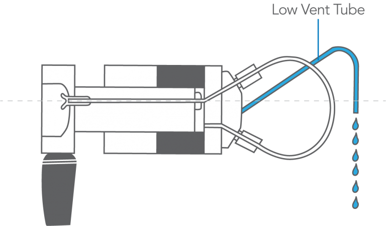
Figure 8: Vent tube high relative to needle port can cause siphoning out needle port.
COMMENTS:
When in the INJECT position, the siphoning may continue until the vent tube and needle port are empty. When in the LOAD position, the siphoning may continue until the vent tube, needle port, and loop are empty.
If you use a long vent tube to go below the fluid level in a low waste reservoir, there will be a large siphoning force and special precautions may be needed. One reason to make such a connection is to prevent evaporation from the end of the tube, which can result in buffer salt crystallization and blockage. If you are loading excess sample to completely fill the loop, air sucked into it prior to inserting the syringe may be displaced. But if you are partially filling the loop, air may not be displaced completely. In this case, you can prevent air from entering the loop by inserting the syringe containing the next sample while still in the INJECT position just before returning to LOAD. This will prevent siphoning from the loop.
When the loop empties due to siphoning, it fills with air, the presence of which can cause the system pressure to decrease when the handle is turned to INJECT. See Symptom 10.
Symptom 3: Leaks at port, vents, or stator — continuously
Symptom 3: Fluid leaks continuously out of the needle port or vent tubes or from between the stator and stator ring (see Figure 9):
- If the system pressure has increased lately — due, for example, to use of a higher flow rate, different column, or partial plugging of a column frit — and especially if it is above 27.6 MPa (276 bar, 4000 psi), Cause A.
- If the system pressure has been stable, see Cause B.
Cause A
The system pressure may have exceeded the current sealing capability of the injector.
Solution: Adjust for higher pressure operation by (depending on the model) either tightening the pressure adjusting screw (see Figure 10) or loosening the set screws and then tightening the stator screws (see Figure 11). For
details see the procedure in the section “Adjusting for Leakage” or “Adjusting Setting of Injector Pressure” in the operating instructions for the injector. See the Operating Instructions section. Also see Appendix B. If adjusting for higher pressure does not eliminate the leak, see Cause B.
Cause B
A scratch on the rotor seal allows high pressure mobile phase to escape. This is referred to as cross-port leakage.
Solution: Replace the rotor seal. Examine the ceramic surface of the stator face assembly and replace if it is chipped or cracked, or if any of the six holes are blocked.
Figure 9: Fluid is shown leaking out of all locations.
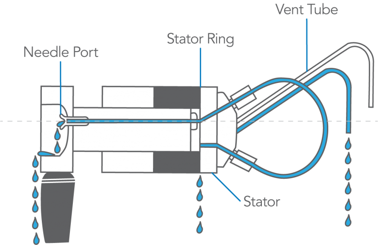
Figure 10: The pressure adjusting screw is tightened using the handle assembly (shaped to serve as a wrench) on models 3725, 7725, 9725, and 9726. Later versions of Models 8125 and 8126 also use this method; early versions use a pressure adjusting nut.
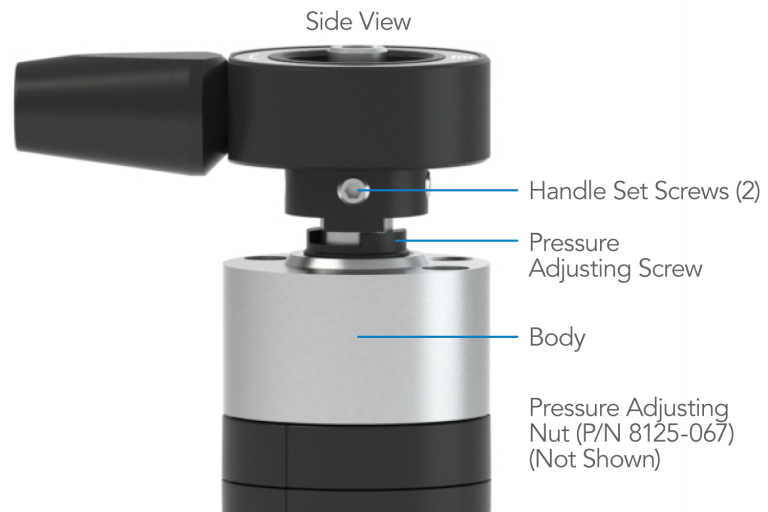
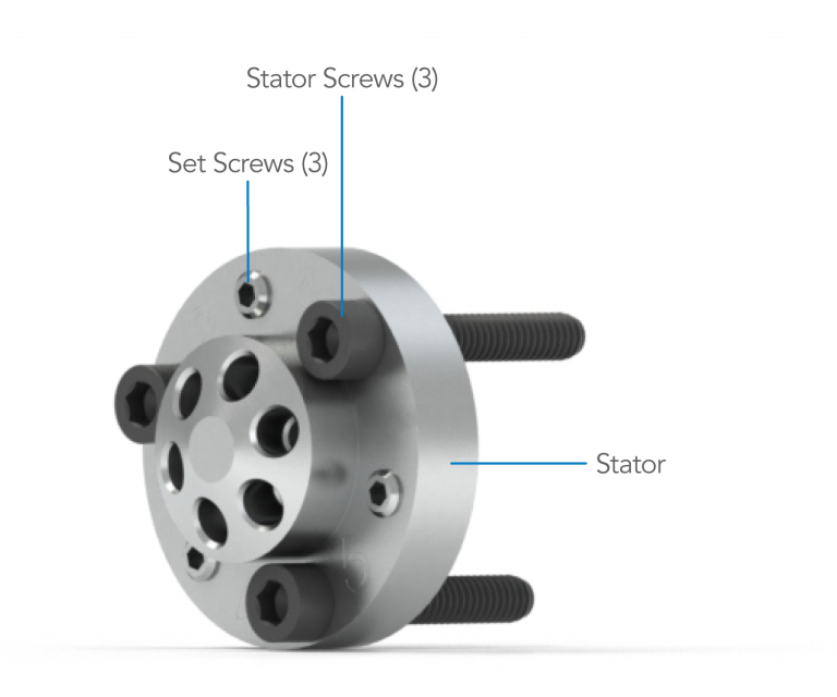
Figure 11: Model 7125 uses set screws and stator screws to adjust for higher pressure.
COMMENTS:
Most models are set at the factory for 34 MPa (340 bar, 5000 psi), but sealing pressure may decrease as the seal wears.
Sometimes a small scratch on the rotor seal can be temporarily “repaired” by adjusting for higher pressure (see Appendix B). Try this if you want to operate temporarily before seal replacement. If the handle becomes harder to turn after adjusting, you should loosen the injector back to the original setting when you install the new rotor seal.
Using a needle with a pointed tip or too small a diameter will severely damage the rotor seal and stator face assembly. The tip can enter port #4 of the stator face, where it is broken off when the handle is turned to INJECT. The protruding tip then scratches the rotor seal. The needle should be 0.7 mm OD (#22 gauge) x 5.1 cm (2 in) long and 90° point style (square-cut end). Do not use a beveled, pointed, or tapered needle.
In some injector orientations, a leak between the stator and stator ring will appear as though the leak is at a fitting in the stator. Likewise, a leak at a fitting may appear as though the leak is between the stator and stator ring. Confirm the true source of the leak before making adjustments.
IIDEX Health & Science RheBuild™ Kits are available for all injectors. Kits contain only genuine IDEX Health & Science parts together with tools and instructions.
Artifact Peaks
Artifacts are peaks that appear unexpectedly. The problems are separated into three groups: carryover peaks, spurious peaks, and distorted peaks:
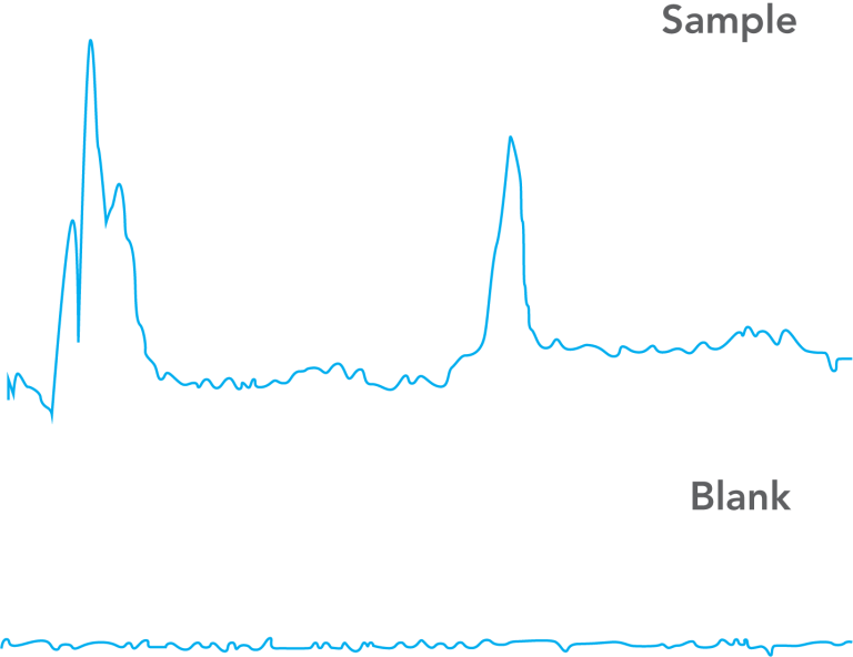
- Carryover peaks are those produced because of cross contamination from a previous injection (see Figure 12). When a blank is injected a miniature chromatogram appears.
- Spurious peaks are those that are unrelated to the previously injected sample (see Figure 13). When a blank is injected, these “ghost” peaks appear as peaks with retention times that are different from sample components.
- Distorted peaks are those that look unfamiliar. A blank injection looks OK, but when the sample is injected some of the peaks are fronting, tailing, or split (double). (See Figure 14.)
- It’s best that you read all parts of “Artifact Peaks,” including the comments, before taking action. You may also want to consider the problem may be caused by a component other than the injector (see Appendix C and Appendix D).
Figure 12: Peaks in blank are CARRYOVER from previous sample.
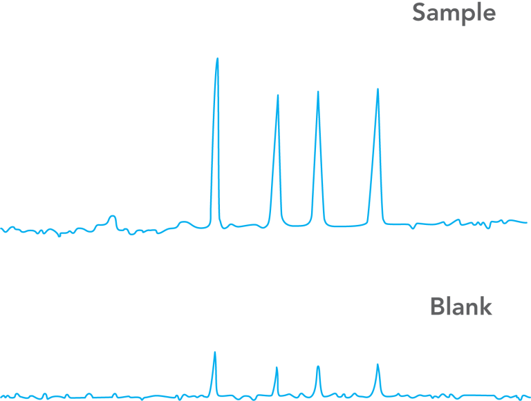
Figure 13: SPURIOUS peaks in blank are unrelated to sample.
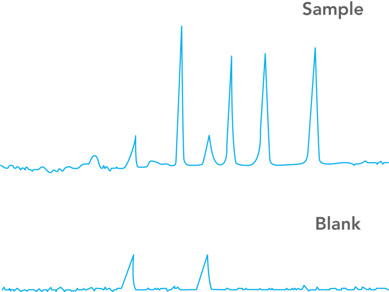
Figure 14: Blank injection is OK, but peaks in sample are DISTORTED.
COMMENTS:
To inject a blank: Inject a volume of mobile phase in the same way that you inject sample. This mobile phase should have exactly the same composition as that pumped at the time of injection. If your sample is dissolved in a solvent different from this, then it is instructive to make an additional blank injection using the sample solvent. This will show if the artifacts are caused by the difference in solvents.
Spurious peaks are more likely when operating at high detector sensitivity and can be a difficult problem to troubleshoot. In some cases they are not real substances, but artificial signals from the detector. In other cases they are real substances, but they come from outside of the injector, either by being unintentionally loaded with the blank or by being desorbed from the column due to the injection of the blank. In rare cases, they are substances that have contaminated the internal parts of the injector.
Use only genuine IDEX Health & Science replacement parts.
Symptom 4: Carryover (miniature chromatogram)
Symptom 4: A miniature chromatogram of the previous sample is produced by injecting a blank. Flush the needle port (see Comments).
Load and inject a blank, using the loading method you have been using — partial-filling or complete-filling (see Figure 15).
- If the peaks are now absent, see Cause A.
- If the peaks are still present, see Cause B.
Cause A
The needle port was contaminated with previous sample. It was pushed into the loop when the syringe was inserted during loading. The flushing step has cleaned the port (see Figure 16).
Solution: If the contamination reappears, make sure you are inserting the syringe properly. You may need to flush the needle port routinely. See Appendix E.
Cause B
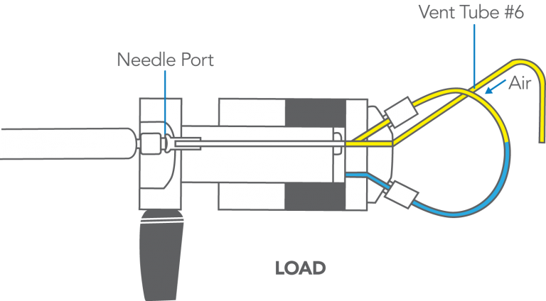
Excess sample from the previous injection was contained in vent tube #6. It siphoned into the loop prior to injection (see Figure 17). If the vent tubes are not properly adjusted, this can occur when in LOAD and the syringe is not in the needle port.
Solution: Adjust the vent tubes so they are level with the needle port (see Symptom 3). Keep the handle in the INJECT position until the next injection and flush just before returning to LOAD:
If the peaks are still present after adjusting the vent tubes, investigate the possibility that the source of carryover is outside of the injector (see Comments).
Figure 15: Droplets of sample remaining in the needle port tube and needle seal. These are absent in normal operation.
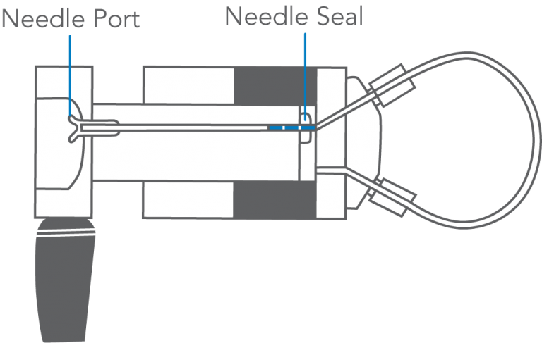
Figure 16: When the syringe is inserted under the conditions shown in Figure 15, droplets of previous sample are pushed into the loop.
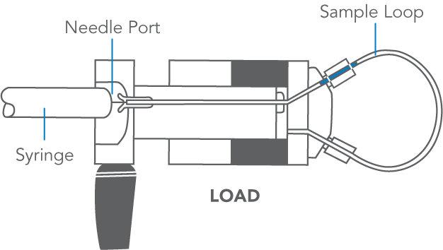
Figure 17: Previous sample siphons from vent tube #6 into sample loop.
COMMENTS:
To flush the needle port: Use from 0.1 to 1 mL of mobile phase. Use a Needle Port Cleaner (IDEX Health & Science Part Number 7125-054) attached to a luer tip syringe. Flush only when the handle is in INJECT so flow goes directly out vent tube #5 and bypasses the loop. This cleans the entire length of the needle port — guide, tube, and needle seal. The cleaner does this because it seals against the front of the guide. A fully inserted needle flushes none of these parts.
If you have no cleaner, use a luer tip syringe. See the illustration in Symptom 5. In routine operation, remove the syringe after turning to INJECT, but keep the handle in this position so the loop is continuously flushed with mobile phase. Flushing after every injection is rarely needed, but, if necessary, do it just before the next analysis. It is usually sufficient to flush after every ten or twenty injections. This keeps liquid in the needle port tube, which baths the syringe needle and dilutes contaminating sample. See Appendix E for more information on when to flush the injector.
There are non-injector sources of sample carryover. These include residual sample in the syringe, contamination in the blank solvent, and contamination in the solvent used for flushing.
Symptom 5: Spurious (unknown) peaks
Symptom 5: Spurious peaks — peaks unrelated to the previous sample or standard — are produced by injecting a blank. Flush the needle port (see Comments). Load and inject a blank using the loading method that you used for the sample (see Figure 18).
- If the peaks are now absent, see Cause A.
- If the peaks are still present: Flush, return to LOAD, and immediately load and inject a blank equal to 1/4 loop volume. Observe peaks. Flush, return to LOAD, and immediately load and inject a blank equal to five loop volumes. Observe peaks.
- If the peaks of the second injection are three to four times larger than the first injection, see Cause B.
- If the peaks of the second injection are not present or are much smaller than the first injection, see Cause C.
- If the peaks of the second injection are the same size as the first, see Cause D.
Cause A
The needle port was contaminated. Flushing has cleaned it (see Figure 19).
Solution: In the future, flush the port routinely.
Cause B
External contaminants from the syringe, glassware, or solvent are inadvertently loaded.
Solution: Use clean utensils. Avoid plastics, which can leach contaminants. Investigate further to see if the artifacts are oxygen peaks (see Appendix D).
Cause C
Trace contaminants within the injector are loaded. For example, contaminants in the needle seal (see Figure 20) are pushed into the loop as the needle enters the seal. When sample is dispensed from the syringe, the contaminants will be flushed completely out of the loop only if a considerable excess of sample is loaded. Contaminants will remain when partial-filling is used.
Solution: Clean the injector (see comments); however other solutions are sometimes easier. If you are using partial-filling, try complete-filling and use a smaller loop if necessary.
Cause D
Trace contaminants within the injector are “injected” simply by switching from LOAD to INJECT or from INJECT to LOAD. To confirm: Flush in the LOAD position (an exception to the rule, see comments on previous page) to clean vent tube #6 (see Figure 21). Then turn to INJECT and wait for any peaks to elute. Ignore them. Now flush normally. While still in INJECT, insert a very clean, empty syringe and keep it in place to prevent remaining contaminants in vent tube #6 or the needle seal from siphoning or diffusing into the loop. Turn the handle to LOAD and start the recorder without turning to INJECT. Wait for peaks to elute. Observe them. Now, with the syringe still in place, turn the handle to INJECT and start the recorder. Observe the peaks. Peaks in either or both of these runs indicate internal contamination, most likely on the rotor seal.
Solution: Clean the injector (see Comments).
Figure 18: Use of the needle port cleaner to flush the injector.
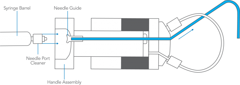
Figure 19: Pathway of the flushing solvent using the needle port cleaner when the injector is in INJECT.
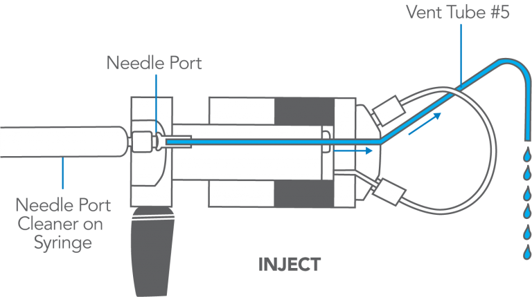
Figure 20: Droplets of sample remaining in needle port and needle seal.
Figure 21: Pathway of the flushing solvent using the needle port cleaner when the injector is in LOAD.
COMMENTS:
Appendix C and Appendix D discuss artifacts mistaken as injector problems.
Ensure vent tubes are properly leveled (see Symptom 2) to prevent contamination from siphoning into the loop.
To flush the needle port: Use 0.1 to 1 mL of mobile phase. Use only a Needle Port Cleaner (IDEX Health & Science Part Number 7125-054) attached to a luer tip syringe. Flush only in INJECT so flow goes directly out vent tube #5 and bypasses the loop. This cleans the entire needle port — guide, tube, and needle seal. The cleaner seals against the front of the guide. A fully inserted needle flushes none of these parts. If you have no cleaner, use a luer tip syringe.
In routine operation, remove the syringe after turning to INJECT, but keep the handle in this position so the loop is continuously flushed with mobile phase. Flushing after every injection is rarely needed, but if necessary, do it just before the next analysis. It is usually sufficient to flush after every ten or twenty injections. This keeps liquid in the needle port tube, which baths the syringe needle and dilutes contaminating sample.
The cement used for syringe needles can leach, especially with chlorinated solvents. If leaching happens, use a removable needle, which has no cement.
To clean the injector: Test after each step to see if the problem is solved. Contamination often is not the problem, and decontamination can be time-consuming. You may want to rule out other causes first.
- Flush the needle port, vent, and tube #6 using a variety of solvents.
- Remove the stator, stator face assembly, and rotor seal (do not disassemble further). Thoroughly clean their passages using a variety of solvents, preferably in an ultrasonic cleaner.
- Replace the rotor seal with a new one of the same polymer composition.
- Replace the rotor seal with a new one of a different polymer composition. In either case, use only genuine IDEX Health & Science parts.
Although we have said that you should flush only in INJECT, it is helpful to flush also when in the LOAD position if you are troubleshooting Cause D. This will clean out vent tube #6, a possible source of contamination that can diffuse back into the loop.
Peaks obtained in the confirming experiments of Cause D can sometimes come from the column, not the injector. See Appendix C.
Symptom 6: Distorted peaks: fronting, tailing, broad
Symptom 6: Peaks are distorted — fronting, tailing, or very broad — and a blank injection is free of peaks. The injector cannot malfunction to cause such symptoms. Check for the following:
- If the sample solvent is not mobile phase, see Cause A. Otherwise, connect a different column which did not previously produce the symptoms:
- If the symptoms are now absent, see Cause B.
- If the symptoms are still present, see Cause C.
Cause A
Sample solvent that is stronger than mobile phase (see Figure 22) causes unsymmetrical early peaks, especially with a large sample volume.
Solution: Use mobile phase for the sample solvent or use a smaller sample volume. If not practical, use a solvent that is as similar as possible.
Cause B
The column or guard column is defective.
Solution: Clean or replace the column or guard column.
Cause C
Loop or column tube connections may have a dead volume (see Figure 23), causing tailing.
Solution: All tubing should be square cut and bottomed in the ports. Replace the loop or column connecting tubes if necessary.
Figure 22: A sample solution (A) that may cause artifacts and one (B) that will eliminate them.
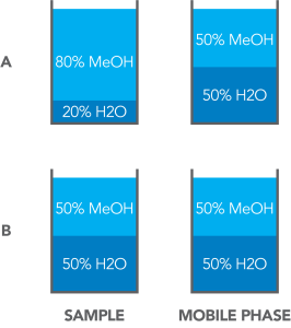
Figure 23: Poor connections result if tubing is not bottomed in the port (A) or is not cut square (B).
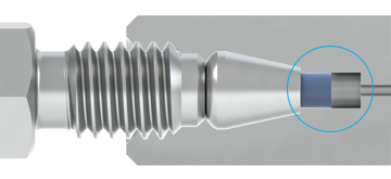
Figure 23-A
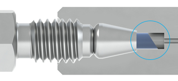
Figure 23-B
COMMENTS:
Peaks that are double, fronting, tailing, or very broad are almost always caused by a column or guard column that is obstructed, contaminated, or worn out.
The chance for artifacts caused by using a sample solvent that is different from the mobile phase is greater when the sample volume is relatively large. For example, when using an analytical reversed- phase column, a mobile phase of 30% methanol in water and a sample dissolved in pure methanol, distortion may be absent when injecting 10 µL, but present when injecting 50 µL.
When using gradient elution, broad peaks that elute among the otherwise normal-appearing peaks can be highly retained peaks from the previous injection(s). This is caused by not programming the mobile phase to a high enough strength and/or not holding it at a sufficient strength for long enough. This can be confirmed by programming to 100% of the strongest mobile phase after the peaks of interest have eluted, and holding at this composition until no more peaks elute. Then, after equilibrating a sufficient time with the initial mobile phase (e.g., five column volumes), inject the next sample and observe the chromatogram.
Non-Reproducible Results
The following sections discuss the problem of poor analytical precision; i.e., the variation in peak height and peak area. The injector cannot affect retention time, except in the very unlikely event of an erratically fluctuating leak that causes variable flow rate in the column.
This section also discusses the problem of a change in peak shape.
When troubleshooting, be aware that there are many causes for nonreproducible results other than the injector.
COMMENTS:
A IDEX Health & Science front-loading injector, properly operated, can inject volumes onto the column with the following precision: 1) Using the partial-filling technique, 0.2% to 2% RSD, depending on operator skill at setting the syringe plunger reproducibly. 2)
Using the complete-filling technique, 0.05% to 1%, depending on the volume loaded relative to the volume of the loop. Loading excess sample of five loop volumes produces about 0.1% RSD. See Appendix E. The observed precision of peak heights and areas depends also on the stability of flow rate, mobile phase composition, and column temperature, and therefore the RSD is usually larger.
Accuracy is the closeness of an injection to the specified sample volume. A front-loading injector can inject volumes with the following accuracy: 1) Using partial-filling, 1% to 2%, depending on the syringe and operator skill. 2) Using complete- filling, 5% to 30%, depending on the loop. This is because loop size designations are nominal. Actual volumes differ because the tubing bore has a 0.001 in tolerance. Accuracy of large loops (2 mL) is about 5%, intermediate loops (20 µL) 10%, and small loops (5 µL) 30%. To find the actual injected volume, calibrate the loop while attached to take into account the injector’s internal passages.
Symptom 7: All peaks have poor area precision
Symptom 7: Peak area and height of all peaks are inconsistent from one injection to another.
- If you require more than one syringe full to load the sample loop, see Cause A.
- If you are loading a volume of sample 50% to 200% of the loop, see Cause B.
- If you are returning to LOAD before ten loop volumes have passed, see Cause C.
- If none of these: Overfill the loop (see Figure 24). Stay in LOAD with syringe in place and plunger depressed.
- If vent leaks continuously, see Cause D.
- If vent does not leak, see Cause E.
Cause A
The syringe is too small. Removing it in LOAD pulls sample from the loop.
Solution: Use a syringe with an appropriate volume
Cause B
You are in the problem zone. See Figure 25, comments, and Appendix F.
Solution: Load the loop with < 50% or > 200% of its volume and be consistent with the rate of loading and the volume loaded.
Cause C
Not all of the sample is swept from the loop.
Solution: Remain longer in INJECT. See Appendix E.
Cause D
A cross-port scratch on the rotor seal allows mobile phase to leak into the loop while in the LOAD position, displacing sample (see Figure 26). To confirm: Load the loop with five loop volumes of sample and inject immediately. This makes an accurate injection of a complete loop volume. Observe the peaks. Load the loop again, but delay turning to INJECT, allowing time for any leakage into the loop to displace sample. Inject and observe the peaks. Smaller peaks indicate leakage. The longer the delay, the smaller the peaks.
Solution: Replace the rotor seal as in Symptom 3. Examine the ceramic surface of the stator face assembly and replace the assembly if it is chipped, cracked, or if any of the six holes are blocked (see Comments).
Cause E
The problem may not be the injector. Check to see if the needle seal is working. When it is loose, not all of the sample dispensed from the syringe enters the loop (see Figure 27). You can discover if the seal is leaking by using the procedures described in Symptom 1. See also Symptom 9 and Comments.
Solution: Re-form the seal if it is leaking. Make sure that you are using the proper syringe needle.
Figure 24: Overfill the loop with at least two to three loop volumes.

Figure 25: The problem zone produces poor precision.
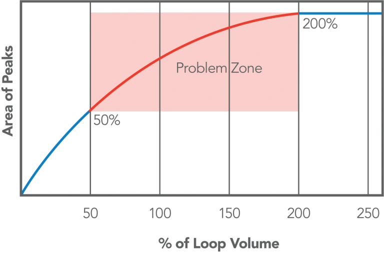
Figure 26: View of the rotor seal with the injector in the LOAD position. A scratch between ports 3 and 4 can displace sample from the loop.
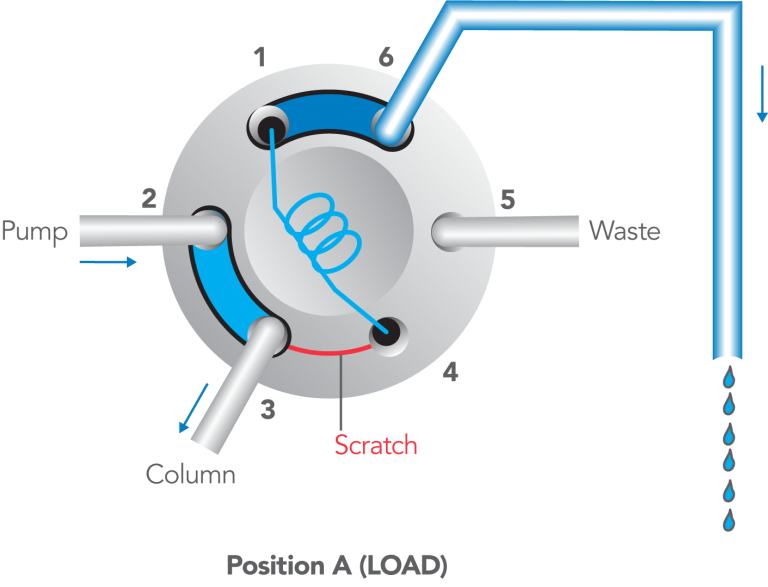
Figure 27: With a bad needle seal (A) sample leaks around the needle seal and into the needle port. With a good needle seal (B) there is no leakage.
COMMENTS:
Precision is poor when the sample dispensed from the syringe is between 50% and 200% of the loop volume. When partial-filling, and the volume dispensed exceeds 50%, some sample is lost out vent tube #6, and the amount lost varies. When complete-filling and the volume dispensed is <200%, much sample remains in the loop and the amount is variable, especially when the volume loaded and the rate of loading are inconsistent. As more sample is loaded, the amount in the loop approaches a constant. See Appendix F for a full discussion of what happens inside the injector.
There are many causes for nonreproducible results other than injector malfunction: Flow rate changes cause nonreproducible retention times and peak areas (area is inversely proportional to flow rate). Peak height is also influenced, but only slightly. Mobile phase composition changes cause nonreproducible retention times and peak heights. Peak areas are relatively unaffected.
Temperature changes cause nonreproducible retention times, peak areas, and peak heights, but the magnitude is usually small and varies with compounds and mobile phases. IDEX Health & Science Technical Note 5 discusses accuracy and precision in LC injection. All IDEX Health & Science literature is available in the Literature & Tools section.
The contribution to nonreproducibility made by the noninjector parts of the system can be determined by making a series of injections with the loop completely full of sample each time an injection is made. Under these conditions, the injector will transfer sample to the column with a volumetric precision of about 0.1%. The amount by which the observed precision of areas and heights is larger is the amount due to the noninjector parts of the system.
To make such a “completely full” injection: Load the loop with ten loop volumes to displace all air and mobile phase. Use the same rate of loading each time. Keep the syringe in the port while turning to INJECT (standard procedure). Inject immediately after loading to ensure that a leaking rotor seal, should it exist, does not have time to displace sample from the loop. During loading, observe that no more than 10% of the sample flows back out the needle port. None should flow out if the needle seal is functioning properly, but this test allows for even a malfunctioning seal. The 10% limit means that at least nine loop volumes will pass through the loop — enough to produce high precision.
IDEX Health & Science RheBuild™ Kits are available for all injectors. Kits contain only genuine IDEX Health & Science parts together with tools and instructions.
Symptom 8: Some peaks have poor area precision
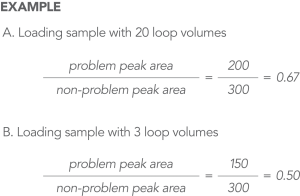
Symptom 8: When using the complete-filling method, the precision of some peaks is much poorer than that of other peaks (see Figure 28).
The poor precision of problem peaks may be caused by their adsorption onto the internal surfaces of the sample loop or the rotor seal. This rare problem is more likely when:
- Using ion pairing reagents and not all sample components form ion pairs.
- The sample solvent is weaker than the mobile phase.
To test: Load sample using twenty loop volumes. Inject immediately. Determine the ratio of a problem peak area to a non-problem peak area. Repeat, using three loop volumes. This passes less total sample over the adsorbing surface, so less will be adsorbed during loading and subsequently desorbed during injection. Inject immediately. Determine the area ratio. Ignore the fact that all peaks in the second chromatogram may have slightly smaller areas than the corresponding peaks in the first chromatogram. - If, in the second chromatogram, the ratio of problem peak area to non-problem peak area is smaller than the ratio in the first chromatogram (see Figure 28), see the cause below.
- If the ratio is unchanged, adsorption is probably not occurring.
Cause
The problem peaks are adsorbing.
Solution: Use mobile phase as sample solvent. Load the same volume using the same flow rate and with the same time interval before injection (see Comments for a detailed explanation).
Figure 28: In this example, sample is adsorbing, since the ratio of problem peak to non-problem peak is smaller with the lower loading volume (three loop volumes) than with the higher loading volume.
COMMENTS:
In most circumstances, internal surfaces of stainless steel loops are inert to all sample components. In the rare cases of adsorption, it can cause poor precision of the adsorbed species. Here is what happens: When using complete-filling (see Appendix F) some components partition onto the loop surface. Upon injection, a mobile phase that is stronger than the sample solvent desorbs these components, causing the mass injected into the column to be larger than that caused by the volumetric transfer. The mass adsorbed depends on the filling conditions: strength of the sample solvent, the excess volume passed through the loop, the loading flow rate, and the delay before injection.
This problem does not occur when loading less than 1/2 a loop volume; all sample is contained in the loop, and there is no opportunity for concentration within the loop, regardless of the filling conditions. One remedy to the problem is to switch to the partial-filling method.
Adsorption sometimes accounts for a large difference in the precision of some peaks observed between two laboratories when the filling conditions of the two labs are different. For example, although both groups may be injecting the same nominal volume, one group may be using partial-filling and the other using complete-filling.
Symptom 9: All peaks are small or absent
Symptom 9: All peaks are very small, or no peaks are observed.
While turning the handle, observe the shaft to which it is attached:
- If the shaft does not rotate, see Cause A.
- If the shaft rotates a full 60°: In the INJECT position, fill the needle port by flushing (see Comments and Figure 29). Turn to LOAD and insert the syringe (a little solvent will appear at the port). Load sample while observing the port and vent tube #6.
- If solvent comes out the needle port while loading but none or very little comes out vent tube #6, sample is not entering the loop. See Cause B
- If solvent does not come out the needle port, but does come out vent tube #6, sample is entering the loop. See Cause C.
Cause A
The knob assembly is slipping on the shaft.
Solution: Tighten the two set screws against the flats on the shaft (see Figure 30). The third screw hole in the knob allows repositioning on the shaft; use only two screws in any one position.
Cause B
The needle seal is malfunctioning (see Figure 29) and/or vent tube #6 is plugged.
Solution: Confirm you are using the proper needle. Clean vent tube #6 if it is plugged. Adjust the needle seal per the tests in Symptom 1.
Cause C
A cross-port scratch on the rotor seal allows mobile phase to leak into the loop while in the LOAD position, displacing sample (see Figure 31). To confirm: Load the loop with five loop volumes of sample and inject immediately. This should inject at least some sample, even if there is leakage into the loop. Observe the peaks. Load again but delay injection, allowing time for leakage to displace a significant amount of sample. Inject and observe the peaks. If the peaks are much smaller, it indicates a leak. If the leak is large, you should be able to observe leakage out vent tube #6 while in the LOAD position and with the syringe inserted.
Solution: Replace the rotor seal as in Symptom 2 (see Comments):
If none of the above is causing the problem, check that the recorder, detector, and pump are operating properly and that the mobile phase strength is adequate to elute sample components (see Comments).
Figure 29: Fill the needle port with solvent using the needle port cleaner.
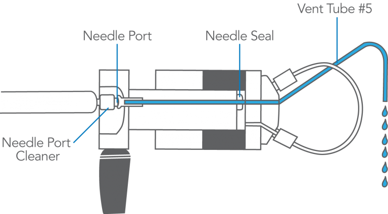
Figure 30: The set screws on the knob assembly need to be tightened on the flats of the shaft.
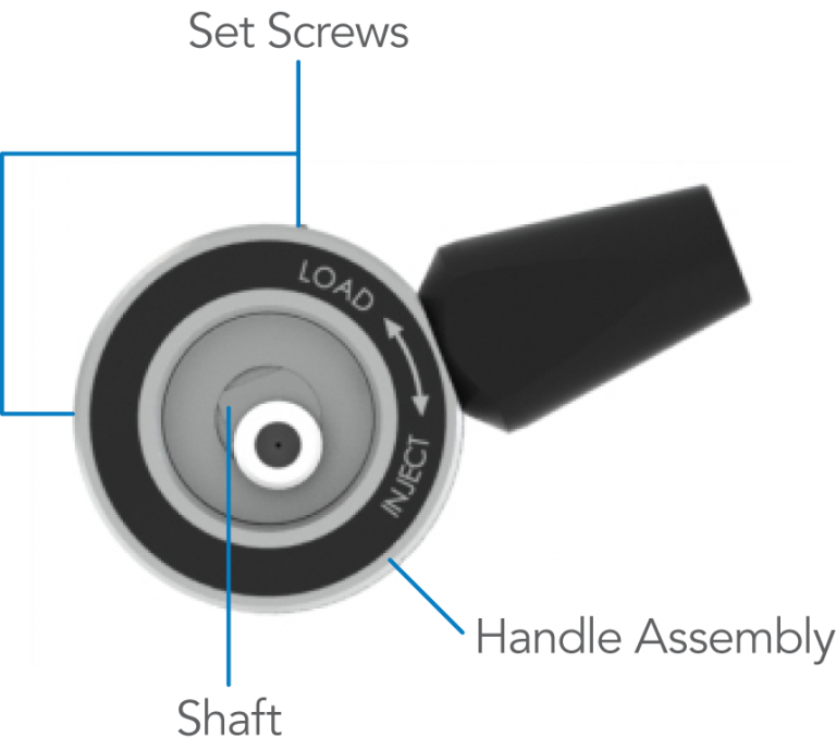
Figure 31: View of the rotor seal with the injector in the LOAD position. Mobile phase (light blue) pushes sample (blue) out of the loop by leaking along the scratch between ports 3 and 4.
COMMENTS:
To flush the needle port and fill it: Use about 1 mL of mobile phase. Use a Needle Port Cleaner (IDEX Health & Science Part Number 7125-054) attached to a luer tip syringe. Flush only when the handle is in the INJECT position, so flow goes directly out vent tube #5 and bypasses the loop. This procedure cleans the entire length of the port — guide, tube, and needle seal-filling it with liquid. If you have no cleaner, use a luer tip syringe. See the illustration with Figure 18.
Mobile phase and excess sample displaced from the loop during loading exits via vent tube #6. It can easily become plugged with buffer salt crystals. If this happens frequently, you should periodically flush the injector in the LOAD position to prevent build up of crystals.
The syringe should be left in the needle port until after injection; otherwise some or all of the sample may siphon out of the loop. See also Symptom 12 for related problems.
To check the detector, adjust the zero, attenuation, gain, and balance controls of the detector and recorder to ensure that the detector signal is being adequately sent by the detector and processed properly by the recorder. You should be able to adjust the baseline to 10% full scale and see noise. If injecting under these conditions does not produce peaks (they will probably be off-scale, however), it suggests that the detector is not the problem and that, for some reason, the components are not reaching the detector.
To check the pump, collect mobile phase exiting the detector to ensure that the delivered flow rate agrees with the value set on the pump controls. If the system uses pumps to generate the mobile phase composition, a low flow rate from one pump can cause the mobile phase composition to be too weak to elute peaks.
Decreased System Pressure
This section discusses the causes of a loss of system pressure that occurs when the injector is switched from LOAD to INJECT or from INJECT to LOAD. Problems involving an increase in system pressure are discussed in the Blockage section.
 7
7
COMMENTS:
There are many non-injector causes of pressure changes. They usually occur as random events, and are not associated with movement of the injector handle. Examples are a leaky check valve in the pump or a partially plugged filter in the mobile phase reservoir.
If the system pressure increases when the injector is switched, see the Blockage section.
Symptom 10: Pressure falls in INJECT position, then returns
Symptom 10: System pressure decreases instantly when the injector is switched from LOAD to INJECT and then slowly returns to a normal level.
- If there is only a small and momentary drop in system pressure, see Cause A.
- If there is a large and momentary drop in system pressure, see Cause B.
Cause A
Air is present in the needle port, specifically the needle seal (see Figure 32). When the syringe is inserted, the needle pushes a small air bubble into the loop. Upon injection, the system pressure collapses the bubble, causing pressure to drop momentarily.
Solution: Remove the air from the needle port by flushing (see Comments). Keep the needle port filled with fluid by occasional flushing.
Cause B
The vent tube(s) is not level with the needle port. This allows air to enter the loop via siphoning, when in the LOAD position (see Figure 33). Upon injection, the system pressure collapses the bubble, causing pressure to drop momentarily.
Solution: Adjust the vent tube(s) so the outlet is at the same horizontal level as the needle port (see Symptom 3).
Figure 32: Air (yellow) present in the needle port is pushed by the syringe during loading into the sample loop.
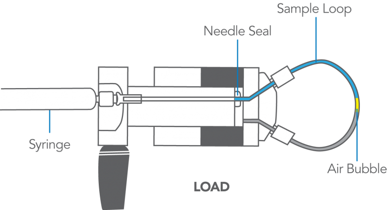
Figure 33: Air (yellow) siphons into loop via vent tube #6 when it is higher than the needle port.
COMMENTS:
To flush the needle port: Use about 1 mL of mobile phase. Use a Needle Port Cleaner (IDEX Health & Science Part Number 7125-054) and only when the handle is in INJECT. This puts fluid in the entire length of the needle port — guide, tube, and needle seal. The cleaner does this because it seals against the front of the guide. A fully inserted needle flushes none of these parts. If you have no cleaner, use a luer tip syringe. See the illustration in Figure 18.
In routine operation, remove the syringe after turning to INJECT, but keep the handle in this position so the loop is continuously flushed with mobile phase. To keep the port filled with fluid, flush every ten or twenty injections.
Air in the loop prior to loading is usually pushed out through vent tube #6 when using the complete-filling method. But, when using partial-filling, not enough sample enters to displace the air; Symptom 10 is therefore more likely to occur when using this method.
The decrease in pressure is instantaneous because the air compresses immediately. It takes the pump awhile to replace the loss of volume and to return to normal pressure. Large loops can produce a large loss of pressure, which takes a longer time to return to normal.
Symptom 11: Pressure falls when injector is switched to either LOAD or INJECT, then stays low
Symptom 11: System pressure decreases when the injector is switched (to either INJECT or LOAD) and does not return to normal (see Figure 34).
Cause
A cross-port scratch on the rotor seal allows high pressure mobile phase to escape. To confirm: Observe the needle port and vent tubes while in the INJECT (or LOAD) position. You will observe the leak at one of these locations. If the needle port or vent tubes were previously full of air, it may take awhile for the fluid to appear.
Solution: Replace the rotor seal. Examine the ceramic surface of the stator face assembly and replace the assembly if it is chipped, cracked, or if any of the holes are blocked. Also see Symptom 2 and comments.
Figure 34: In the LOAD position (A), a scratch between ports 3 and 4 allows high pressure mobile phase (light blue) to leak into the needle port. In the INJECT position (B) the scratch moves between ports 4 and 5. The mobile phase now leaks out vent tube #5.
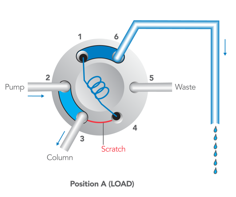
Figure 34-A
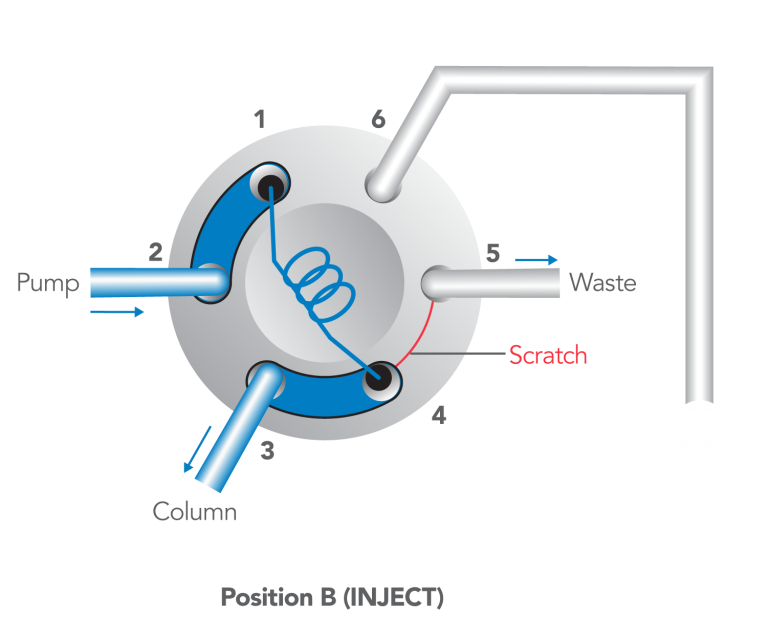
Figure 34-B
COMMENTS:
There are four possible cross-port scratch locations on the rotor seal:
- When in the LOAD position, a scratch between ports #3 and #4 will allow fluid to escape in both the LOAD and INJECT positions.The figure illustrates this case.
- When in the INJECT position, a scratch between ports #2 and #3 will not produce leakage outside of the system although it will cause some flow to bypass the loop. When the rotor seal is turned to LOAD, this scratch is now between ports #1 and #2, allowing fluid to escape from vent tube #6 or the needle port.
- When in the LOAD position, a scratch between ports #5 and #6 will not produce high pressure leakage. When the rotor seal is turned to INJECT, this scratch is now between ports #1 and #6, allowing fluid to escape from vent tube #6.
- When in the LOAD position, a scratch between ports #4 and #5 will not cause leakage in either position, but it may allow some sample to bypass the loop during loading if the loop has a high resistance to flow and sample is dispensed rapidly.
IDEX Health & Science RheBuild™ Kits are available for all injectors. Kits contain only genuine IDEX Health & Science parts together with tools and instructions.
Blockage – High Back Pressure
The following pages discuss the causes of complete or partial blockage in the injector. The problem has two cases. 1) The loop is difficult to load. In this case, the system pressure (pressure at the pump) may be either normal or high. 2) The loop is not difficult to load, but the system pressure is high. These problems are most commonly encountered when using buffer salts in the mobile phase.
COMMENTS:
There are many materials that can block injector passages, including crystallized buffer salts, suspended matter in the sample or mobile phase, burrs from tubing and fittings, and particles from pump seals. The following routine procedures will prevent blockage:
- Filter particles from the mobile phase and, when necessary, the samples.
- Install a filter between the pump and injector to protect the injector from wear particles from the pump.
- Rinse the injector periodically, especially before shutting down, when using buffers for mobile phase or sample solvent.
- Use burr-free tubing and fittings to avoid metal shavings.
Symptom 12: Cannot load loop
Symptom 12: The sample loop cannot be loaded or offers excessive resistance when loading sample.
- Locate the blockage by attempting to load sample under the following conditions (use Figure 35 as your guide):
- Remove vent tube #6 (A). If the resistance is gone, see Cause A, otherwise,
- Remove the loop. If resistance is still there, see Cause B, otherwise,
- Reconnect the loop only at port #4. If resistance returns, see Cause C, otherwise,
- Reconnect the loop at both port #1 and #4. If resistance returns, see Cause D.
Cause A
Particles are blocking vent tube #6 (A).
Solution: Remove and clean the vent tube. In the future, flush this tube periodically, especially if the mobile phase or sample contain buffer salts, which can crystallize when the solvent evaporates (see Comments).
Cause B
Particles are blocking the needle seal or the stator passages associated with port #4 (see Figure 36).
Solution: In LOAD, with the loop removed, flush the needle port two or three times using the needle port cleaner (see Comments).
Cause C
Particles are blocking the loop.
Solution: Clean or replace the loop.
Cause D
Particles are blocking the stator, stator face assembly, and rotor seal passage (B) associated with port #1 (see Figure 37).
Solution: Clean these passages. Try using the pump at high flow rate with the loop removed and the handle in the INJECT position (see Figure 38). In the future, you may need to flush these passageways periodically, especially if the mobile phase or sample contain buffer salts, which can crystallize when the solvent evaporates (see Comments).
Figure 35: Flow diagram of the injector in the LOAD position.
Figure 36: Enlarged view of the needle seal and stator face assembly showing particles (green) blocking the passage.
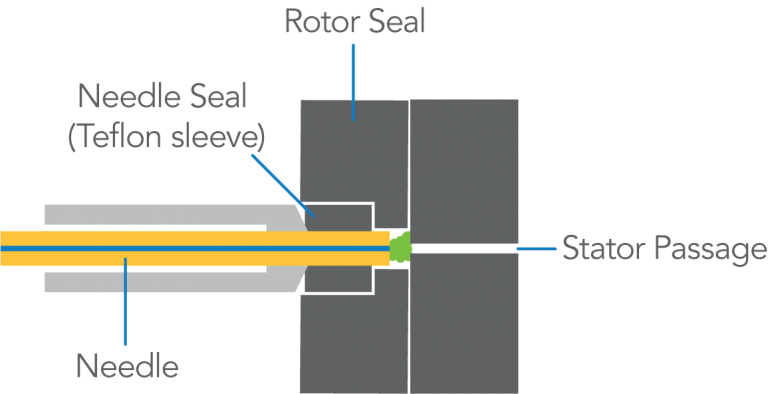
Figure 37: Detailed view of passageways where particles can obstruct flow.
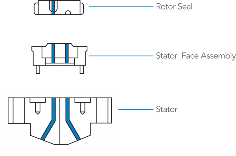
Figure 38: Flushing out the passageways associated with port #1, in the INJECT position.
COMMENTS:
In Cause A, if cleaning the tube does not solve the problem, clean port #6.
The normal procedure for flushing the needle port is: Use about 1 mL of mobile phase. Use a Needle Port Cleaner (IDEX Health & Science Part Number 7125-054). Flush only when the handle is in the INJECT position so flow goes directly out vent #5 and bypasses the loop. If you have no cleaner, use a luer tip syringe. See Figure 18 in Symptom 5.
In solving Causes A and B, make an additional flush when the handle is in LOAD in order to flush the passages of ports #4 and #6 and vent tube #6. If the purpose of flushing is to remove buffer salts, do it with water, not organic solvents.
In routine operation, remove the syringe after turning to INJECT. However, keep the handle in this position so the loop is continuously flushed with mobile phase. We recommend keeping the needle port filled with fluid by flushing every ten or twenty injections. Flush just before the next analysis.
Backflushing ports with the pump set at high flow rate is sometimes effective in cleaning certain passages.
Cleaning the loop or stator passages can usually be achieved by immersing the individual parts for at least five minutes in an ultrasonic cleaner using a variety of solvents.
Backflushing ports with the pump set at high flow rate is sometimes effective in cleaning certain passages.
A .25 mm (.010 in) OD or smaller wire can be used to remove particles that do not dissolve.
See also Symptom 9 for related problems.
Symptom 13: High system pressure
Symptom 13: The system pressure is unusually high, either constantly or only during movement of the handle:
- If the pressure increases when the handle is turned, then returns to normal, see Cause A.
- If the pressure remains high in either the LOAD or INJECT position, locate the blockage, with the handle in the INJECT position, by observing the pressure under the following conditions. Note Figure 39 and Figure 40.
- Disconnect the column connecting tube at port #3 (A). If pressure returns to normal — about zero psi, depending on the flow rate, connecting tubing, and sample loop — see Cause B, otherwise,
- Disconnect the pump connecting tube at port #2 (B). If pressure remains high see Cause C, otherwise,
- Reconnect the pump. Remove the loop. If pressure remains high, see Cause D, otherwise,
- Reconnect the loop only at port #1. If pressure remains high see Cause E, otherwise see Cause F.
Cause A
The interruption of flow, which occurs with some models (see Comments) when the handle is turned, causes a momentary increase in backpressure.
Solution: Turn the handle faster.
Cause B
The column or column connecting tube (A) is plugged. The injector is OK.
Solution: Replace or clean them.
Cause C
The pump tube (B) is plugged, or the pump is malfunctioning. The injector is OK.
Solution: Troubleshoot the pump. Check the pump tube (B) in case it is plugged.
Cause D
Particles are blocking port #1, port #2, or the rotor seal groove (C).
Solution: Clean them. See Comments for a procedure.
Cause E
Particles are blocking the loop.
Solution: Clean or replace it. See Comments for a procedure.
Cause F
Particles are blocking port #3, port #4 , or the rotor seal groove (D).
Solution: Clean them. See Comments for a procedure.
Figure 39: Flow diagram of the injector in the INJECT position.
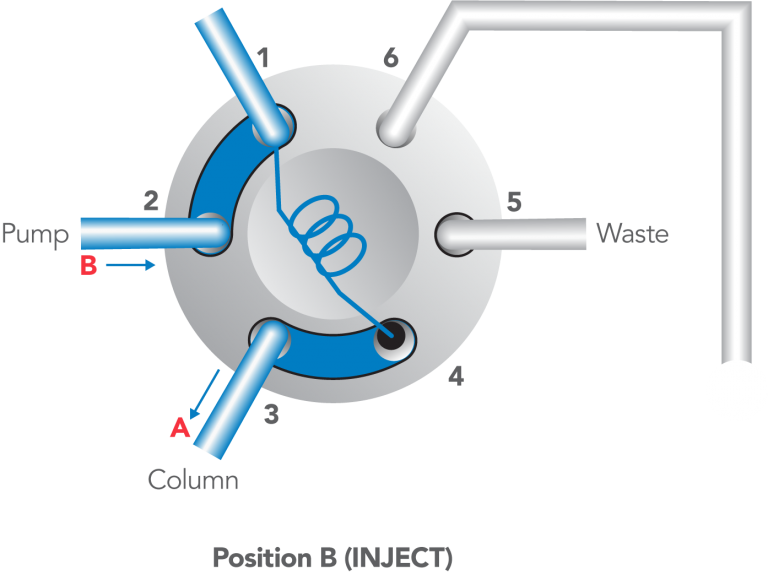
Figure 40: Flow diagram of IDEX Health & Science’s patented make-before-break (MBB™) design.
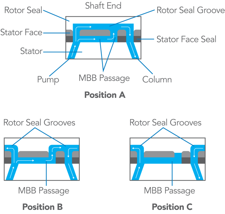
Figure 41: Flow diagram of the injector in the INJECT position.
COMMENTS:
Some injectors, like the Model 7725, have a patented continuous-flow design. When turning the handle, a passageway in the stator face makes the new flow connections before the old connections break (“make-before-break,” or MMB™, design). There is no momentary interruption of flow.
Other injectors, like the Model 7125, interrupt the flow during movement of the handle from one position to the other. Figure 40 shows such a model. When the rotor seal is rotated back to the LOAD position (clockwise since this is a view from the rear), you can see for a time that the pump is not connected to either port #1 or port #3. This causes a transient: In the pump line the pressure rises and the flow stops; in the column line the pressure falls and the flow stops. The magnitude of these effects increases when the handle is turned slowly, the flow rate is high, or the pumping system has a low compliance. Usually the transient has no effect on the system, but when using flow-sensitive detectors, fragile columns, or pumps that are disturbed by flow or pressure changes, injectors having IDEX Health & Science’s continuous flow design may be preferred.
- To remove a blockage, use the following procedures. After each step, test to see if flow has been restored before proceeding to the next step.
- Backflush the injector in both the LOAD and INJECT positions by disconnecting the column and connecting the pump to port #3. Use the highest flow rate achievable by the pump.
- Clean the stator, loop, and/or vent tubes for at least five minutes with an ultrasonic cleaner using a variety of solvents.
- Use a .010 OD or smaller wire to clean out the stator face assembly holes.
- Clean out the rotor seal channels, being careful not to scratch the polished surface.
- Replace the parts. If crystallized buffer salts have caused blockage, prevent future problems by periodically flushing the injector, especially prior to shutting down the system. See Appendix E for the flushing procedure.
Noise or Drift
A detector baseline that has excessive noise or drift is rarely caused by the injector, at least not directly. But improper operation of the injector can cause gas to collect in the detector cell, making it oversensitive to subtle (normal) changes in ambient conditions.
COMMENTS:
There are many non-injector causes of a noisy baseline. For example, the detector or recorder electronics may be a source of noise. If so, the frequency of the noise will be independent of changes in the flow rate setting, or the pump may cause regular flow fluctuations.
If so, the frequency of the noise will be inversely proportional to the flow rate setting.
Compounds leached from plastic syringes, vials, and from the cement used to attach needles to syringes can cause noise and drift in electrochemical detectors.
Symptom 14: Noisy or drifting baseline
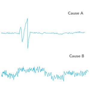
Symptom 14: The baseline is noisy or drifting (see Figure 42).
If switching to LOAD or INJECT causes a momentary detector baseline disturbance instantaneous with the handle movement, see Cause A.
- If the baseline is constantly noisy, or drifts excessively, see Cause B.
Cause A
The flow interruption that occurs each time the handle is turned causes a pressure disturbance in the detector. Interruption is normal with some IDEX Health & Science injectors, see the Blockage section comments. Most detectors do not respond to this, but a detector taht has become oversensitive to pressure changes will respond. Oversensitivity can be caused by a cracked cell window, by dirt or gas bubbles in the cell.
Solution: Test for oversensitivity (see Comments). Flush out gas bubbles with degassed mobile phase. Adjust the injector, if necessary, to ensure that it is not injecting air (see Symptom 10).
Cause B
The detector may contain gas, causing oversensitivity to slight flow and temperature fluctuations.
Solution: Test for oversensitivity (see Comments). Flush out gas bubbles with degassed mobile phase. Adjust the injector if necessary, to ensure that it is not injecting air (see Symptom 10).
Figure 42: Examples of noisy baseline
COMMENTS:
There are many non-injector causes of a noisy baseline. For example, the detector or recorder electronics may be a source. If so, the frequency of the noise will be independent of changes in the flow rate setting, or the pump may cause regular flow fluctuations. If so, the frequency of the noise will be inversely proportional to the flow rate setting.
Compounds leached from plastic syringes, vials, and from the cement used to attach needles to syringes can cause noise and drift in electrochemical detectors.
Appendices
Appendix A: Injector Drawings with Part Numbers
Select the model number of the valve to download a PDF of the exploded view of that valve’s parts.
7125 7725 / 7725I 9725 / 9725I
Appendix B: Adjusting the Pressure Setting of Injectors
Model 7125
The three stator screws in the valve stator are used to adjust the pressure setting. The valve has been factory set to hold 34 MPa (340 bar, 5000 psi). If there is leakage between the stator and stator ring, then proceed as follows. Unscrew the three set screws part-way out from the stator. Tighten down the three stator screws until they just start to grip, then tighten an additional 1/4 turn. Reconnect the valve to your system and pump solvent through at about 500 psi above the normal operating pressure or the pressure to which you want the valve adjusted.
If there is a leak, continue to tighten the three stator screws 1/8 turn each until the leak stops (see Leaks: Symptom 3, Figure 11). Confirm that the gap between the stator and stator ring is the same width all the way around. Finish by screwing in the set screws until they touch the stator ring.
Models 8125/8126 (manufactured through 6/92)
A single pressure adjusting screw at the shaft-end of the valve body is used to adjust the pressure setting. The valve has been factory set to hold 34 MPa (345 bar, 5000 psi). If there is leakage between the stator and stator ring, proceed as follows.
Remove the knob assembly and slip the pressure adjusting nut onto the valve shaft so the tabs on the nut fit into the slots in the adjusting screw. Tighten the adjusting screw about 1/20th of a turn. Use the twenty dial markings on the body and the painted spot on the adjusting screw as guides.
If the new setting does not stop the leakage, repeat the procedure by tightening an additional 1/20th turn. Finish by replacing the knob and retightening the two knob set screws onto the flats on the shaft.
Models 3725, 7725/7726, 9725,9726 (and Models 8125/8126 manufactured after 6/92)
A single pressure-adjusting screw at the shaft end of the valve body is used to adjust the pressure setting. The valve has been factory set to hold 34 MPa (340 bar, 5000 psi). If there is leakage between the stator and stator ring, proceed as follows.
The knob assembly is designed with two tabs that can be used to turn the adjusting screw. To use it, loosen the two set screws in the knob so the knob slips down the shaft and the tabs fit into the slots on the adjusting screw. Tighten the adjusting screw about 1/20th of a turn. Use the twenty dial markings on the body and the painted spot on the adjusting screw as guides.
If the new setting does not stop the leakage, repeat the procedure by an additional 1/20th turn. Finish by replacing the knob and retightening the knob set screws onto the flats on the shaft.
Helpful HintsIf the valve is not mounted on a panel, or if the adjusting screw is difficult to turn, loosen each of the three stator screws before adjusting the adjusting screw. Be sure to retighten these screws when you are finished and before testing.
Appendix C: Non-injector Sources of Artifact Peaks
A blank injection can produce artifact peaks that are not really coming from the injector.If the unknown peak occurs instantaneously with the movement of the injector handle (i.e., a retention time of zero minutes), then it is probably due to a pressure disturbance in the detector. This disturbance is caused, in some cases, by the brief flow interruption that occurs each time the handle is turned. Whereas most properly functioning detectors will not respond to such a pressure disturbance, a detector that has become oversensitive will respond. Oversensitivity is caused by a gas bubble in the cell or a cracked window. If you can produce a detector response by making slight changes in the cell pressure (partially restricting the outlet), this condition probably exists.
If the unknown peak has a retention time greater than zero (quite often it is an unretained peak, i.e., k’=0), then probably a substance is actually being “injected” onto the column. However, the substance is not necessarily coming from the injector. It may be coming from contamination of the column frit or the top of the packing. Such contamination can be desorbed by an injection in which the sample solvent has a composition different from the composition of the mobile phase. It may also be that such contamination can be desorbed by the flow transient caused by handle movement.
Peaks are sometimes observed in gradient analysis with a blank injection. These ghost peaks usually come from the initial or final eluent. Using purer solvents or shortening the equilibration time between runs may eliminate the problem.
Helpful Hints
To remove air from the detector, pump degassed mobile phase and put a back-pressure regulator at the detector outlet to produce pressure — typically <0.7 MPa (6.8 bar, 100 psi) — within the cell. Adjust the injector so it does not inject air (see Symptom 10).
In isocratic analysis, you can determine if a contaminant is being desorbed from the top of the column instead of coming from the injector by injecting a blank. Do this by connecting tubing between the injector and column, a volume that will make an observable increase in retention time. For example, 100 cm of 0.8 mm (.030 in) OD tubing contains 450 µL, shifting retention about 0.5 minute at 1 mL/min. If the retention times increase, the substances are from the injector or sample. If the retention times do not change, the substances are from the column.
Confirm by connecting the tubing between the column and detector. If the retention times now increase, the substances are from the column. The tubing will cause the peaks to be broader, but hopefully the retention times will still be measurable. This test only works with isocratic analysis.
You can confirm that peaks in a gradient run are not associated with the injector by connecting the column directly to the pump (bypassing the injector) and running the gradient.
Appendix D: Oxygen Peak Artifacts
Artifact peaks are sometimes produced when the sample (or blank) contains oxygen in a concentration that differs from the oxygen concentration in the mobile phase that is flowing at the time of injection. This difference is common when the mobile phase is completely degassed, such as when continuously sparged with helium. The mobile phase arriving at the injector will contain essentially no oxygen, but the solvent in which the sample is dissolved will contain oxygen unless it has been degassed immediately prior to injection.Such artifacts are particularly noticeable when a UV detector is operated at high sensitivity and at a low wavelength. They also occur with electrochemical detectors, where the peaks can be positive or negative.
The following procedure will show if oxygen is the problem. First remove a 1 mL aliquot of mobile phase from the chromatograph’s reservoir. Immediately inject a blank using some of this solvent. Observe the peaks. They may be very small or nonexistent. Now agitate the remaining aliquot for at least two minutes to equilibrate it with air. Inject another blank using this solvent. Observe the peaks. If the peaks of the second injection are larger and correspond to the retention times of the artifacts, it indicates that the problem is differences in oxygen concentration.
You can further confirm this by making blank injections of mobile phase that contain differing amounts of oxygen. For example, compare injections of mobile phase that has been sparged (in the vial prior to taking it into the syringe) with helium, nitrogen, air, or pure oxygen. The relative amount of oxygen in these three gases is 0.0, 0.2, and 1.0, so the peak heights in the three cases should have this ratio.
Helpful HintsThe UV absorbance of dissolved oxygen itself is very small, but it is believed that dissolved oxygen forms complexes with solvent molecules, and that these have appreciable absorbance. With mixed solvents, more than one complex species would be expected. Indeed, with mixed mobile phases more than one peak is often observed.
You are more likely to encounter artifact peaks when using an efficient degassing system. Oxygen in the air will dissolve in degassed mobile phase very rapidily. The more thorough the degassing, the greater is the driving force to reabsorb oxygen. If peaks appear when they have previously been absent, check to see if a procedure has changed that might have changed the oxygen concentration in either the mobile phase or the sample. Oxygen can enter the mobile phase by diffusing upstream against the outflowing helium in the reservoir vent tubes and by diffusing through PTFE reservoir-to-pump transfer tubes.
Appendix E: Flushing Procedures
After turning to INJECT, remain in this position long enough for the pumped mobile phase to flush all sample from the loop. This provides maximum precision and eliminates the need for any further flushing of the loop. Do not manually flush it; you cannot do a better job than the pump. Pump at least ten sample volumes. For example, if you load 20 µL into a 100 µL loop and pump at 1 mL/min, stay in INJECT at least 12 seconds.You can then return to LOAD, or you can stay in INJECT until ready to load the next sample. Remove the syringe from the needle port at any time before returning to LOAD.
Flushing the needle port after every injection to prevent cross-contamination is normally not necessary. IDEX Health & Science’s patented direct-connection port design connects the tip of the syringe needle directly to the end of the sample loop; there is no connecting passage to trap sample that would otherwise be pushed into the loop when the next sample is loaded.
Trace amounts of sample sometimes are deposited in the needle seal region during insertion and withdrawal of the syringe. Careful measurements have indicated that this residue is only 1 to 10 nL. This represents from .005% to .05% of a 20 µL injection. If desired, you can eliminate this trace by flushing the needle port after each injection.
If you observe more cross-contamination than this, make sure that you are not inadvertently creating a connecting passage due to:
- Using a needle that is too short so the needle tip does not touch the stator face. Minimum length from hub to needle tip should be 5.1 cm (2 in).
- Not fully inserting the syringe into the needle port.
- Dirt particles or needle seal shavings in the needle port that prevent the needle tip from touching the stator face.
Even when cross-contamination is not a concern, it is good practice to flush the needle port every ten or twenty injections. This keeps liquid in the needle port tube, which bathes the syringe needle and dilutes any sample that contaminates this region during movement of the syringe into or out of the port. It also keeps the needle port and vent tube #5 filled with solvent, preventing air from inadvertently entering the sample loop.
Helpful Hints
To flush the needle port, use from 0.1 to 1 mL of mobile phase. Use a Needle Port Cleaner (IDEX Health & Science Part Number 7125-054) attached to a luer tip syringe. Flush only when the handle is in the INJECT position so flow goes directly out vent #5 and bypasses the loop.
This procedure cleans the entire length of the needle port — guide, tube, and needle seal. The cleaner does this because it seals against the front of the guide. A fully inserted needle flushes none of these parts. If you have no cleaner, use a luer tip syringe.
When inserting the syringe into the needle port in the LOAD position, the needle pushes a small amount of liquid (from the last flushing of the needle port) out of the needle seal region and into the loop. When this liquid is different from the mobile phase, and when you are partial-filling the loop, it can cause artifact peaks at high detector sensitivity. So mobile phase is the best liquid to use when flushing the needle port.
Appendix F: What Happens Inside the Injector
Mobile phase in the loop is displaced when you dispense sample from the syringe during loading. The boundary between the sample and mobile phase has a parabolic profile due to laminar flow; the velocity at the center of the tubing is twice the average velocity, and at the wall it is almost zero. So, sample in the center travels 2 µL along the loop for every 1 µL dispensed.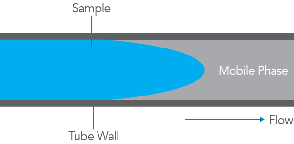
This behavior accounts for the shape of the curve in the graph, a plot of sample volume dispensed from the syringe vs. mass of sample injected into the column. The curve has three regions.
- When the volume dispensed is less than half the loop volume, the curve is linear. Sample has not yet reached the far end of the loop. Within this region, performance depends on syringe accuracy and the operator skill. Accuracy is typically 1% if you use the syringe full-scale volume. Precision is 0.2% to 2% RSD, depending on your skill. This is the region of the partial-filling method.
- When the volume dispensed is between half a loop volume and about two loop volumes, the curve is nonlinear. Sample is lost from the loop, so accuracy and precision are poor. If you dispense a volume equal to the volume of the loop, you are in this region of inferior performance.
- When the volume dispensed is several loop volumes, the mass injected is independent of the volume dispensed. The loop contains only pure sample, undiluted by residual mobile phase. Accuracy is determined by the loop. Precision is 0.05% to 1%, depending on the volume loaded. Five loop volumes produce about 0.1% precision. When only a few loop volumes are loaded, in order to conserve sample, precision is improved by loading nearly the same volume each time. This is the region of the complete-filling method.
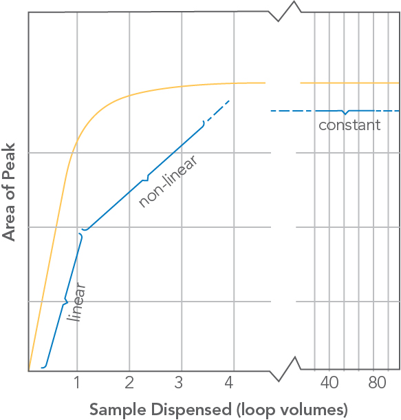
Volume of sample dispensed (in units of loop volumes) from the syringe vs. sample mass (observed peak area) injected onto the column for a IDEX Health & Science front-loading injector.
Helpful Hints
IDEX Health & Science front-loading injectors have a built-in needle port with a patented direct-connection design. It connects the tip of the syringe needle directly to the end of the sample loop. There is no connecting passage that traps sample, which can enter the loop when the next sample is loaded. Syringe accuracy is maintained and flushing after every injection is rarely necessary.
Size designations of sample loops are nominal. Actual volumes can differ from the nominal designations because of the tolerance of the tubing bore. Accuracy of large loops (2 mL) is about 5%, intermediate loops (20 µL) 10%, and small loops (5 µL) 30%.
The following IDEX Health & Science Technical Notes contain useful information:
Technical Note 5, “Achieving Accuracy and Precision with IDEX Health & Science Sample Injectors.”
Technical Note 7, “Pressure Drop of Valves and Tubes from 1 to 1000 mL/min.”