IBS Coatings for Ultrafast lasers and Applications
Introduction
The generation of ultrashort laser pulses is now routinely achieved by commercial laser systems. Depending on the architecture of the laser cavity the generation of pulsed light in the nanosecond, picosecond and femtosecond time regimes is possible. Even within the realm of femtosecond pulsed lasers it is possible to construct a cavity designed to emit pulses as short as 5 fs or pulses as “long” as 500 fs. The majority of femtosecond lasers used today are based on a design that yields laser pulses of 100 fs in duration, with relatively high repetition rates and high average powers. Depending on the choice of lasing medium - Ti:sapphire crystal, Ytterbium- or Erbium-doped materials are commonly used - it is possible to generate such femtosecond laser pulses in the ultraviolet (UV), visible, near-infrared (NIR) and mid-infrared (MIR) parts of the electromagnetic spectrum. One of the most common examples is a femtosecond Ti:sapphire laser with a cavity design that supports ~100 fs pulses at a 80 MHz repetition rate, with several milliwatts (mW) of average power, and is continuously tunable over 680-1080 nm. This type of laser is widely used in two-photon fluorescence microscopy and other nonlinear imaging applications [1].
Common to all such femtosecond lasers is the need to deliver the emitted pulses from the output of the laser to their final destination (e.g., the sample) while maintaining the temporal integrity of the pulse. When ultrashort laser pulses are transmitted through or reflected off of optical components such as lenses and mirrors, temporal broadening due to dispersion occurs. One way to minimize the unwanted effects of dispersion is to use high-performance dielectric thin-film coatings specifically designed to precisely control and manage the effects of material and other dispersion contributions over a broad wavelength range.
Dispersion considerations for femtosecond laser applications
From the point of view of femtosecond laser applications it is necessary to compensate the effects of material dispersion. For transmissive optics the primary source of pulse broadening is the thickness of the glass itself. To minimize pulse broadening effects the use of thinner substrates is required. By way of example, a 100 fs pulse centered at 800 nm broadens to ~101 fs upon transmission through a piece of fused silica a few mm thick. Typically such small increases can be tolerated in most applications, though for shorter pulse lengths, or complex systems with several pieces of glass, pulse broadening can be significant. For reflective optics dispersion is dominated by geometric effects and can readily lead to pulse broadening factors several tens of percentages or even several times more. After multiple reflections a 100 fs laser pulse can easily be transformed into a pulse several hundred femtoseconds wide. For this reason it is critical to design dielectric thin-film coatings which minimize the effects of geometric dispersion. The effects of both material and geometric dispersion on femtosecond laser pulses upon transmission or reflection are shown schematically in Figure 1.
Equipped with an intuitive physical picture of pulse broadening it is now worthwhile taking a moment to consider from a mathematical perspective what happens to femtosecond laser pulses when they interact with dispersive media, and then understand how this drives various technical considerations when designing thin-film coatings for a given end application. Here we consider what happens to a femtosecond laser pulse upon reflection from an optical element, such as a high reflectivity mirror. Due to geometric dispersion upon reflection, the incident laser pulse experiences a phase shift. Mathematically the amplitude of the reflected pulse Erefl can be written as:
 ,t) = Einc( ,t) |r( )|e
where Einc denotes the amplitude of the incident pulse, |r()| ethe amplitude reflectivity of the mirror, is the optical frequency, and t denotes time. The term represents the frequency-dependent phase change experienced by the
incident pulse. If one considers the phase at optical frequency close to some center optical frequency  then the phase term can be approximately represented by the first few terms of a Taylor series, yielding:

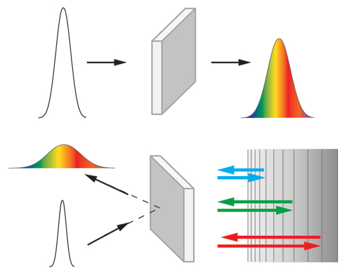
Figure 1: Schematic showing the effects of dispersion on ultrashort laser pulses. (Top) A femtosecond laser pulse is temporally broadened as it is transmitted through a piece of uncoated glass due to material dispersion. Here the red wavelengths emerge from the glass before the blue wavelengths (positive dispersion). (Bottom, left) A femtosecond laser pulse is temporally broadened as it is reflected off of a dielectric mirror due to geometric dispersion. (Bottom, right) The effects of pulse broadening upon reflection are readily understood based upon the different path lengths experienced by different wavelength in an ultrashort laser pulse. For the negative dispersion mirror shown, the red wavelengths penetrate further into the mirror coating and are delayed with respect to blue wavelengths. Specially designed mirrors such as this can be used to compensate for the positive dispersion (i.e., positive chirp) that can be picked up by the pulse as it passes through other optical components such as laser crystals and lenses.
The first term in the above equation is a constant phase effect that is generally not detectable. The second term is the first-order derivative and represents the group delay (GD) experienced by the pulse. It describes the additional time it takes the pulse to enter and then emerge from the mirror coating. If GD≠0 (and all higher-order terms are negligible) over the pulse bandwidth the reflected pulse is merely delayed in time, with no spectral broadening. The third term is the second-order derivative and represents the group delay dispersion (GDD). If GDD≠0 the pulse is temporally broadened and becomes positively chirped for GDD>0 and negatively chirped when GDD<0. Here positively chirped means longer wavelengths lead, or arrive earlier than shorter wavelengths. Careful consideration must be given to this term when optimizing optical coatings for laser pulses having duration below about 1 ps and as short as about 50 fs. The fourth term represents the third-order dispersion (TOD). For applications involving sub-30 fs laser pulses the TOD term should also be fully optimized in the thin-film coating design.
High-performance ion-beam sputtering (IBS) coatings for dispersion management
Today there exist a variety of options when it comes to thin-film coatings for dispersion management in femtosecond laser applications. Metallic coatings are one example, where relatively high (> 95%) reflectivity and very low group delay dispersion are possible over a very broad range of wavelengths. However, all metals absorb some light, and therefore are susceptible to damage in applications involving high intensity lasers. Susceptibility to laser-induced damage can be reduced by making a hybrid metal-dielectric coating. Although this approach may provide adequate protection for a period of time, typically one observes a decrease in mirror performance over extended times, and even part failure. As a result it is often necessary to replace the mirrors, which can become a costly and unnecessary exercise, especially if a user is running an important experiment. Coatings based on dielectric materials are the ideal solution to this problem since they can now be designed to meet the demands of today’s advanced femtosecond laser technology.
All-dielectric mirror coatings constructed using alternating high and low index thin-film layers and based on quarter wave stack (QWS) designs are a simple and straightforward option to provide dispersion-compensated coatings. Mirror designs that provide near zero dispersion over a narrow range of wavelengths are ideal for applications where the femtosecond laser is either set at a fixed wavelength, or tuned over a fairly narrow (100-150 nm) wavelength range. However, such mirrors do not provide well controlled, low GDD at either extremities of the available reflection band thus limiting the utility of QWS designs. At these wavelengths regions where the reflection is slightly decreased, and therefore the transmission is higher, the penetration depth of the light (i.e., the electric field) increases. Consequently the phase delay experienced by the incident pulses increases significantly, with GDD values of several hundred fs2 typical. When low dispersion at a different wavelength is desired it is possible to manufacture QWS mirror designs where the center wavelength is located more in the visible or NIR; however, this typically requires a custom coating run that can delay an end users experiment unnecessarily.
As the trend towards the development of femtosecond laser systems which can be continuously tuned across a broad (~400 nm) wavelength range grows, it is therefore necessary to develop mirror coatings that provide low, well-controlled dispersion characteristics which allow users to fully exploit the inherent capabilities of these lasers. One solution is to employ all-dielectric, non-QWS IBS thin-film coatings that provide high reflectivity, well-defined and reliable dispersion (GDD) performance, and high laser damage threshold (LDT) over a broad wavelength range. The reflectivity and group delay dispersion (GDD) performance of two broadband turning mirrors designed for use with a widely tunable Ti:sapphire laser having pulse widths > 50 fs is shown in Figure 2.
The main benefits of the turning mirror designs shown are the high (> 99.3%) reflectivity and well-defined group delay dispersion over a 450 nm bandwidth for both s- and p-polarized light. For applications where the femtosecond laser is to be tuned across its full usable bandwidth, having a well-defined GDD is important. As evidenced by the plot on the right of Figure 2, both mirrors satisfy this requirement. For the s-polarized mirror design (red) the group delay dispersion (GDD) is contained within +/- 100 fs2 about 0 fs2, where for the p-polarized mirror design (green) the GDD is contained within +/- 50 fs2 about -50 fs2 over the wavelength shown. As such, these mirrors are ideal for use with the tunable Ti:sapphire femtosecond laser systems commonly used in multiphoton microscopy.
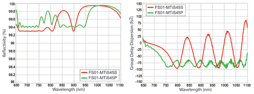
Figure 2: Reflectivity (left) and group delay dispersion (GDD, right) versus wavelength for two broadband, dispersion compensated turning mirrors designed to operate at 45° for both s-polarized (red) and p-polarized (green) light. Both mirror designs exhibit high (> 99.3%) reflectivity and low, well-defined GDD over the wavelength range shown. Designs for use at small angles of incidence (0-10°) are also possible.
As highlighted above, broadband high reflectivity, low dispersion dielectric mirrors are the ideal choice for beam steering applications involving widely tunable femtosecond lasers. However, there exist a myriad of different mirrors and optics that are used in ultrafast laser applications, with each requiring a unique coating design. A type of mirror commonly used on the laboratory bench top is one in which the coating design is tailored to impart a precise amount of large negative dispersion. Such mirrors are known as Gires Tournois Interferometer (GTI) mirrors. GTI mirrors can be configured as single elements or as pairs in the light path. In the latter case each mirror has a well-defined negative (or positive) GDD profile over a range of wavelengths. When set up to allow multiple reflections between a mirror pair it is possible to impart several hundred or even several thousand fs2 of dispersion, making this simple arrangement a cost-effective means with which to (pre-)compensate for the build-up of large amounts of positive GDD from, for example, the optical components in an optical microscope. An example of a single dielectric mirror designed to provide high reflectivity (R > 99.9%) and large negative dispersion (-1200 fs2) around 1030 nm is shown in Figure 3.
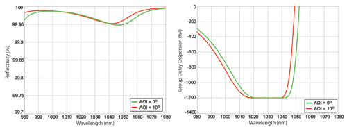
Figure 3: Reflectivity (left) and group delay dispersion (right) versus wavelength for a large negative dispersion mirror designed to be used over 0 to 10o for s-polarized light. The designed mirror provides R > 99.9% over a wavelength range of 100 nm, while providing group delay dispersion (GDD) of -1,200 fs2 over a bandwidth of ~20 nm centered at 1030 nm. The ripple in the GDD is < +/- 2 fs2 over 1020-1040 nm.
Another type of optic commonly used in femtosecond laser applications is the beamsplitter. Beamsplitters are typically used to pick off a small fraction part of the incident laser beam for pulse diagnostics or to seed a second laser, such as an amplifier system. Once again, it is critical to carefully control and manage the dispersion imparted onto the incident laser beam, especially for the reflected light. Any additional phase imparted onto the pulses upon transmission is dependent on the thickness of the part. Specially designed ion-beam-sputtering (IBS) coatings offer users the ability to employ beamsplitters that have different (fixed) splitting ratios and which provide low, well-defined reflected and transmitted GDD over a broad range of wavelengths. Examples of octave spanning beamsplitters designed for use with femtosecond laser pulses having duration > 30 fs are shown in Figure 4.
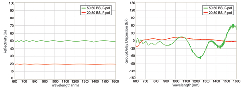
Figure 4: (Left) Linear reflectivity versus wavelength for two octave-spanning beamsplitters designed to work at 45°. The beamsplitters shown were designed to reflect 50% (green) and 20% (red) respectively across a broad (1000 nm) wavelength range for p-polarized light. The ripple in the reflectivity is less than +/- 1%. (Right) Reflection group delay dispersion (GDD) versus wavelength for the two beamsplitter designs shown. Designs for s-polarized light are also possible.
Dispersion compensated coatings for lasers with pulses shorter than ~ 30 fs are also possible. Additional types of laser mirrors and other optical components commonly used in femtosecond laser applications are described in Table 1.
Table 1: Description of various different types of ion-beam-sputtered (IBS) optics commonly used in femtosecond laser applications.
IBS-Coated Femtosecond Optics | Description |
High reflectivity (HR), low dispersion broadband mirror | High-reflectivity (HR) mirror used to guide light around an optical table. Designs for s- & p-polarized light and for operation over 0-10° and 45° across a broad (>400 nm) wavelength range. |
Low dispersion (GDD) mirror Mirror Pair | HR mirror that provides zero GDD over a narrow wavelength range. Paired mirrors with GDD profiles designed to compensate one another to help reduce the GDD ripple over a broad range of wavelengths. |
Large negative GDD mirrors (GTI mirrors) | Mirrors exhibiting large negative dispersion to compensate for the build-up of positive GDD. Designs having negative GDD values within the range -100 to -1,000 fs2 or more are possible depending on the bandwidth. |
HR intracavity mirror | Low loss, high-reflectivity (R>99.95%) mirrors for use within a laser cavity. |
Broadband beamsplitters (45°) | Used to split off part of the laser beam for pulse diagnostics and /or to seed other lasers. Various splitting ratios (R:T= 10:90; 20:80; 30:70) for s- & p-polarized light are possible. |
Dichroic beamsplitters | Dichroic beamsplitters used to separate different wavelength regions in the UV, visible and NIR. Commonly used in multiphoton microscopy. |
Intracavity IBS-coated mirrors for femtosecond lasers
Ultrafast laser performance strongly depends on the spectral properties, reflected phase and dispersion and the quality of optical coatings used in the laser resonator and amplifiers. Here, highly customized thin-film all-dielectric coatings with high-reflectivity, low loss, well-defined dispersion across a broad range of wavelengths (i.e., the entire gain bandwidth of the laser medium), and high laser induced damage threshold are required in order allow for efficient operation of the laser and the generation of femtosecond scale pulses. An example of such an intracavity mirror is shown in Figure 5. For the mirror considered here the thin-film dielectric coating was designed to provide reflectivity greater than 99.93% and low dispersion over a bandwidth of 450 nm for a laser cavity intended to generate pulses on the order of 10 fs.
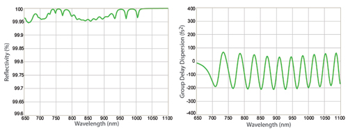
Figure 5: Reflectivity (left) and group delay dispersion (right) versus wavelength for a laser cavity mirror designed to provide high reflectivity and low dispersion across a broad wavelength range for use inside a femtosecond laser cavity. The mirror was designed to operate at small angles of incidence.
Manufacturing dispersion-compensated thin-film coatings using ion-beam sputtering (IBS)
A comprehensive understanding of how best to optimize the balance between the reflectivity and dispersion properties of a thin-film coating design for femtosecond laser applications is critical. Equally important is a understanding and control of the deposition process to ensure that the theoretical design is accurately replicated in the finished product. Common approaches used in the deposition of high-reflectivity, dispersion compensated coatings are electron-beam (e-beam) evaporation and ion-beam sputtering (IBS).
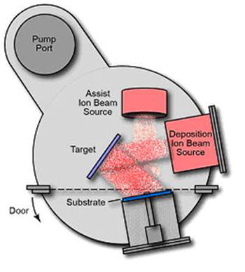
Figure 6: Schematic of an ion-beam-sputtering (IBS) coating chamber. An ion gun is used to bombard the target material with the ejected atoms deposited on a rotating substrate. Shutters are used to control material deposition at the substrate as the coating is deposited layer by layer. The optical monitoring system is not shown.
Ion-beam sputtering offers several unique and differentiable advantages for high performance optical coatings. Because the material atoms are deposited at high energy (~ 10 eV), densely packed thin-film layers are formed. These result in optical coatings that are chemically inert and mechanically stable under a wide variety of environmental conditions, leading to optics that operate and function as designed over extended lifetimes - often several years. Dispersion compensated coatings that can withstand high peak intensities, whether they are used inside a laser cavity or for guiding the laser beam around an optical table, are a must. Additional key attributes of the IBS coating process include its ability to produce coatings with low absorption, low defect densities, and high laser damage threshold (LDT). An important aspect that differentiates IBS from other deposition techniques for the production of ultrafast laser mirrors is the ability to precisely monitor and control the thickness of each individual layer throughout the entire deposition process thus minimizing layer errors. In this way it is possible to reliably and repeatedly manufacture multilayer coatings where each deposited layer has a thickness that matches the design and results in mirror coatings with spectral and phase performance characteristics that remain true to the initial design. As such IBS is the premier choice for the manufacture of high-reflectivity (R> 99% and even 99.9%) dispersion compensated mirror coatings. A comparison between evaporation and sputtering techniques is presented in Table 2.
Table 2: Comparison of different deposition techniques used in the manufacture of high reflectivity mirrors.
| Electron Beam Evaporation | Ion-Beam Sputtering (IBS) | |
| Number of layers | < 100 | > 200 |
| Surface Roughness (Å) | 4 to 10 | < 1 |
| Absorption (ppm) | > 10 | < 1 |
| LDT (J/cm2)* | 5 to 30 | > 50 |
| Reflectivity (%) | < 99.9 | > 99.9 |
| Density/porosity | Porous | Dense |
| Adhesion | Good | Excellent |
| Deposition Rate | Very high | High |
| Large Area Substrates (>12”) | Yes | No |
* Measured using 1064nm, 20 ns pulsed laser light.>
Measuring What you Make - Optical Metrology for Dispersion Characterization
Having the right optical metrology tools with which to assess the overall spectral performance of any thin-film coating is important for the development of highly repeatable coating processes as well as post-production quality control. For the case of IBS-coated thin-film interference filters used in fluorescence and Raman applications, for example, a spectrophotometer is typically used to measure the transmission and blocking levels and accurately locate the edge locations of the designed transmission and reflection bands, thereby ensuring these meet the design specifications. The same standard also applies to thin-film coatings designed for femtosecond laser applications. Given the sensitivity of femtosecond pulses to broadening due to dispersion, accurate measurements of the dispersion properties of manufactured parts is critical and allows end users to efficiently manage system-level dispersion with confidence.
One of the most straightforward measurement methods available with which to accurately characterize the dispersion properties of an optical component is based on white light interferometry [3,4]. Interferometry-based approaches provide a rapid and accurate means with which to quantitatively measure the frequency-dependent phase experienced by an incident light beam after transmission (or reflection) as a function of wavelength from the test part. A white-light interferometer configured in a Michelson geometry used for dispersion measurements is shown in Figure 7. The input white light is split into two equal parts at the beamsplitter (BS). One half of the input beam is transmitted to the reference arm where it is reflected back along its original path by a mirror (M1). The second portion of the beam is reflected to the test arm, where, in this example, it is subsequently reflected back along its original path by the test mirror (M2). The beams recombine at the beamsplitter and their time-dependent interference is measured as the path length of one arm is changed by a known distance. By taking the Fourier Transform of the measured time-domain interferogram it is possible to extract the group delay (GD), group delay dispersion (GDD), and third-order dispersion (TOD) over the detector bandwidth and fully characterize the dispersion properties of the optical coating under test.
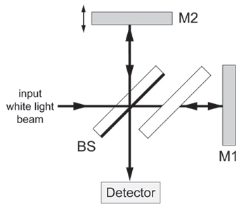
Figure 7: Schematic of a white-light interferometer capable of measuring the dispersion properties of a variety of test (M2) components. BS – beamsplitter; M1 – reference mirror; M2 – test optic. Additional details on the operation of the interferometer shown above can be found in Ref 4.
To demonstrate the capabilities of such a white-light interferometer, broadband, high-reflectivity turning mirrors (Semrock PulseLineTM FS01-MTiS45S and FS01-MTiS45P) having well-defined dispersion (GDD) profiles were tested. The resultant measurement data is displayed in Figure 8. From a direct comparison of the theoretical and measured GDD profiles, it is clear that the dispersion performance of the manufactured part accurately matches the expected GDD performance over the wavelength range shown, and clearly highlights the superior manufacturing capabilities of the IBS coating process.
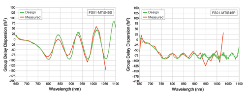
Figure 8: Plot of group delay dispersion (GDD) versus wavelength for Semrock’s FS01-MTiS45S and FS01-MTiS45P broadband, high-reflectivity turning mirrors designed for use at 45° for s- & p-polarized light respectively. The green line represents the theoretical dispersion profile. The red line represents the measured GDD profile and was obtained using the white-light interferometer approach described here. The white-light interferometer has an accuracy of +/- 5 fs2.
Femtosecond lasers in action
Femtosecond lasers are an enabling technology for numerous applications. Some of the most common uses for femtosecond lasers include: material processing (e.g., micromachining of metals); biomedical (e.g., stent cutting); ophthalmology (e.g., LASIK eye surgery); life-science imaging (e.g., multiphoton microscopy); basic scientific research (e.g., femtochemistry and attosecond pulse generation); and the push for renewable energy sources (e.g., high-intensity, petaWatt laser sources that could one day drive nuclear fusion events). In each of the examples listed it is paramount that the effects of dispersion are properly controlled and managed such that pulse broadening effects are minimized or compensated. Two examples for which femtosecond lasers are a truly enabling technology are described below, with an emphasis on the detrimental effects of broader pulses in each application.
Multiphoton Microscopy
In the 1990’s the development of solid-state femtosecond laser technology helped propel multiphoton microscopy (MPM) from a limited number of the most sophisticated research laboratories into a much more widely accessible application. In all microscopy techniques the goal is to obtain high signal-to-noise ratio (SNR) images that clearly elucidate the structure and behavior of the sample under investigation. In multiphoton microscopy the biological samples of interest tend to be sensitive to and easily destroyed by too much laser power. So the average power must be kept below a certain threshold. Yet the strength of the multiphoton emission depends super linearly on the peak power of the pulses (e.g., it goes with the square of the peak power for two-photon fluorescence imaging). Since the repetition rate for a given laser is constant, the peak power is related to the average power, repetition rate and pulse width by:
It is therefore, critical to deliver the shortest possible laser pulses in order to achieve the highest peak powers for the highest contrast imaging in a given sample.
The impact of pulse broadening in two-photon (2P) microscopy is demonstrated here via a simple experiment. A 2P fluorescence microscope equipped with a tunable Ti:sapphire laser at 870 nm was used to acquire images from GFP-expressing primary motor neurons from a live zebrafish sample. In the first experiment the laser pulse width was set at 75 fs and a series of images was acquired. With all other experimental parameters kept constant the laser pulse was broadened to 125 fs and repeat images were acquired. Figure 9 comparesshows the result of both experiments. From the acquired images it is evident that the resultant reduction in peak power delivered to the sample has a detrimental effect on the overall image quality.
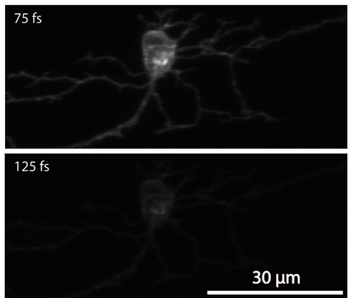
Figure 9: The effects of pulse broadening on two-photon (2P) fluorescence imaging. 2P excited fluorescence images of GFP-expressing primary motor neurons taken in a live zebrafish using 870 nm laser pulses. The pulse durations are shown in the top left hand corner of both images. The excitation power, detector gain and other settings were the same in both sets of experiments. Image credit: Steve Tilley, Joseph DiPietro, Joseph R. Fetcho, and Chris C. Schaffer (Cornell University).
Femtosecond laser material processing
Pulsed lasers have found growing use in laser-machining applications that require a high degree of control and precision to ablate and cut a variety of different materials, with nanosecond and picosecond lasers commonly deployed. Femtosecond lasers are also used and owing to their shorter pulse widths offer unique advantages over longer pulsed lasers. Due to their high peak power and short pulse duration, femtosecond lasers can be used to cut, drill or mark with minimal thermal damage to the sample. Most materials heat up on picosecond timescales. When femtosecond lasers are used there is not sufficient time for the material lattice to absorb the light energy. Therefore, thermal damage can be reduced significantly with the net result being lines and holes with limited collateral damage. A comparative example of the effects of laser pulse width in ultrafast laser material processing is shown in Figure 10.
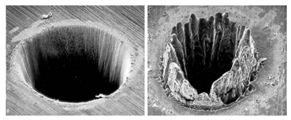
Figure 10: Comparative example of the use of femtosecond laser pulses (left) versus nanosecond laser pulses (right) when drilling micro holes in stainless steel. See Ref [5]. Image credit: Dr. Stefan Nolte.
Maintaining the temporal integrity of femtosecond lasers pulses is critical to a wide variety of applications. One simple way to limit the effects of pulse broadening is to select the right optical components which effectively and efficiently manage dispersion. Whether the optics are used inside a laser cavity, for laser beam steering, or for pulse diagnostics a wide range of design options are available. Ion-beam-sputtered (IBS) thin-film coatings provide the necessary spectral, dispersion, and high LDT properties for today’s advanced femtosecond laser technology.
Authors
N. Anderson, L. Wang, and T. Erdogan
References
[1] W. Zipfel, et. al., Nature Biotechnology, 21, 11, 1369-1377 (2003).
[2] A. Weiner, Ultrafast Optics, Wiley Series in Pure and Applied Optics, 1st Ed., (2009).
[3] W. Knox, et. al., Optics Letters, 13, 7, 574 – 576 (1988).
[4] S. Diddams and J-C. Diels, J. Opt. Soc. Am. B, 13, 6, 1120 - 1129 (1996).
[5] B. N. Chickov, et. al., Applied Physics A, Mat. Sci. Proc., 63, 109-115 (1996).
Acknowledgements
The authors acknowledge Prof. Chris Schaffer and his research group for kindly providing the two-photon excited fluorescence images used in Figure 9.