Flatness of Dichroic Beamsplitters Affects Image Quality
Optical filters are generally comprised of multi-layered thin-film coatings on plane, parallel glass substrates. All Semrock filters use a single substrate with coatings on one or both sides to maximize transmission and reliability. The glass substrate is not always perfectly flat before coating and the intrinsic stress of hard coatings can cause slight bending of the substrate. Fortunately, this bending has no noticeable effect on light transmitted through an optical filter at or near normal incidence. For light incident at high angles of incidence, like for a 45° dichroic beamsplitter, the bent substrate creates a slight divergence of the transmitted beam axis similar to the effect of a small wedge in the substrate. Unless the radius of curvature is very small (much less than one meter) the quality of the transmitted beam remains largely unaffected.
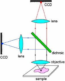
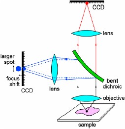
Reflected light, however, is significantly impacted by a bent filter substrate. This situation typically arises when an excitation beam is reflected off of a dichroic beamsplitter before reaching a sample, or when an imaging beam is split into two colors using a dichroic beamsplitter. Two main effects may occur: (1) the position of the focal plane shifts and (2) the size (or shape) of the focused spot changes or the quality of the image is compromised.
Focal plane shift
In most cases, a small shift of the focal plane is not problematic because a lens or camera adjustment can be made to compensate for the shift, but there are certain applications in which a focal shift cannot be tolerated. For example, when a laser beam is reflected off of a dichroic beamsplitter in a Total Internal Reflection Fluorescence (TIRF) microscope arranged in the epifluorescence configuration, the laser beam must be focused at the back focal plane of the objective and too much focal shift caused by a bent dichroic can make it impossible to achieve this condition.
When light is reflected off of a spherically curved surface with radius R, the light behaves as if it were transmitted through a lens of focal length R/2. If the light is subsequently focused by a lens of focal length f, the curvature causes a focal shift (Δf) compared to reflection off of a flat surface. Based on a first-order optics approximation, the relative focal shift is Δf/f ~ 2f/R. In order to maintain a relative focal shift Δf/f below a certain required value, the radius of curvature of the bent filter surface needs to exceed

Suppose a laser beam is reflected off of a dichroic beamsplitter before being focused to a spot at the sample plane by a 40X, 0.75 NA microscope objective, which has a focal length of f = 5 mm, and suppose we want to keep the focal shift below 5 µm, or the relative focal shift below 0.1%. Then the radius of curvature of the dichroic must be greater than about 10 meters.
When working with gaussian beams (often an excellent model for a laser beam), the depth of focus is quantified by the "Rayleigh Range," which is the distance from the beam waist (smallest focused spot) to the point where the waist has increased by a factor of √2. Practically, the Rayleigh Range defines the depth of focus because a beam (or image point) focused to a location within one Rayleigh Range of the waist appears to be in focus. If we use the criterion that the focal shift should be less than one Rayleigh Range, then the radius of curvature of a reflecting filter in front of a focusing lens should exceed

where D is the diameter of the beam at the focusing lens and λ is the wavelength of light. Note that the required radius of curvature is independent of the focal length of the lens. As an example, for a 1 mm diameter laser beam the radius of curvature
of the dichroic should be greater than about 3 meters. Semrock's laser-quality dichroic beamsplitters are generally specified with a maximum beam diameter, D, for which the focal shift will be less than one Rayleigh Range at the edge wavelength of
the beamsplitter. For instance, the Di02-R488-25x36 is a BrightLine® Laser Dichroic which will
cause less than one Rayleigh Range of focal shift for a 488 nm laser beam as large as 2.5 mm in diameter. For a 1 mm diameter beam, the focal shift will be less than 1/6th of the Rayleigh Range. For advanced microscopy applications our
Super-resolution / TIRF grade of Flatness dichroic beamsplitters provide optimal solutions for much larger beam diameters, by minimizing
reflected wavefront distortions.
As an image-splitting example, let's assume a 40X, 0.75 NA microscope objective, for which the beam diameter is about 7.5 mm. Thus the radius of the dichroic must exceed about 160 meters for yellow-green light, in order to observe no noticeable focal shift. For such advanced microscopy applications our Image-splitting grade of Flatness dichroic beamsplitters provide optimal solutions for much larger beam diameters for image-splitting applications.
Compromised image quality
When light incident at 45° is reflected off of a dichroic beamsplitter with a slight bend, then third- and higher-order aberrations (such as astigmatism) can degrade the quality of a focused spot size (for a collimated beam) after a focusing lens or of an image after an imaging lens. These effects can be accurately modeled using ray optics with standard optical modeling software. As an example, the graph shows the spot size obtained at an image plane that results from a perfect point source object after reflecting off of a dichroic beamsplitter with various radii of curvature.
This plot is based on a typical epifluorescence microscope configuration, assuming a perfect point source at the sample location, imaged onto the image plane (e.g., CCD surface) by an ideal 40X, 0.75 NA objective and a tube lens with a 180 mm typical focal length (industry standard tube length focal lengths range between 160 and 200 mm). The resulting beam diameter is 6.75 mm. The reflection off of the dichroic is assumed to occur mid-way between the objective and the tube lens. The field of view of the system is assumed to be limited by a 20 mm diameter field size at the camera plane. The light is assumed to have a wavelength of 510 nm (peak of GFP emission). For comparison, the diffraction-limited spot size that would result from a perfect objective and tube lens and a perfectly flat dichroic is 16.6 μm.
Reflected image quality can be worse than the ideal diffraction-limited response for dichroics that are not perfectly flat, though it should be noted that the true spot size at the image plane can be appreciably larger than the diffraction-limited spot size in an actual system. Nevertheless, care should be taken to select properly optimized, flatter dichroic beamsplitters when working with reflected light. Dichroics designed to reflect laser light ("Laser" or "Super-resolution / TIRF" [7] Flatness dichroics) ensure negligible focal shift for laser beams up to several mm in diameter even for most demanding applications such as Super-resolution and TIRF microscopy utilizing large diameter beams. Dichroics designed to reflect imaging beams ("Image-splitting" grade of flatness dichroics) have the most extreme flatness requirements, since they must effectively eliminate the effects of astigmatism for beams as large as 1 cm or more. For complete listing of Image-splitting dichroics review our product page.
Learn more about how Semrock can help you achieve the best image registration:
White Papers:
Feature articles in BioPhotonics:
Achieving the Best Alignment for Fluorescence Images (August 2005)
Optical Filters Affect Image Fidelity (November 2003)