Flatness of Dichroic Beamsplitters Affects Focus and Image Quality
1. Introduction
Even though fluorescence microscopy has become a routine technique for many applications, demanding requirements from technological advances continue to push the limits. For example, today biological researchers are not only interested in looking at fixed-cell samples labeled with multiple colors, but they are also interested in looking at the dynamics of live specimens in multiple colors, simultaneously. Even certain fixed-cell imaging applications are hampered by limited throughput of the conventional multicolor imaging techniques. Given that the most popular multicolor fluorescence imaging configurations – including “Sedat” and “Pinkel” [1] – are often too slow, new multicolor imaging approaches are evolving. The schematic of such an imaging setup that enables “simultaneous” visualization of multicolor images of a specimen is shown in Figure 1.
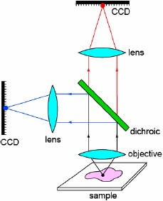
Figure 1: A simple setup for simultaneous visualization of two colors.
In this example, the dual-colored emission signal from the sample is split into two emission light paths using a dichroic beamsplitter, and the signal in each of these channels is imaged onto a CCD camera. An advantage of this configuration over conventional multicolored imaging configurations is that the emission signal from multiple sources can be visualized simultaneously. Due to the absence of any moving parts, such as a filter wheel, this approach enables high-speed image acquisition, thus allowing for very fast cellular dynamics to be imaged in multiple colors at the same time. The principal of splitting the emission signal into different channels is already possible using commercially available products that allow for multichannel imaging. For example, standard video adaptors available from microscope companies can be attached to the emission port of a microscope. In another approach, multiple- channel imaging systems like “Dual View” and “Quad View” (Photometrics) and “OptoSplit” (Cairn Research) are based on the same principle, but instead of steering the emission signal of different colors onto two different detectors, different regions of the same CCD chip simultaneously image different colors.
These are just a few examples, which illustrate the application of an “imaging dichroic,” or a dichroic in which not only the signal transmitted through the filter, but also the signal reflected off of the dichroic is imaged onto a CCD camera. Considering the expected growth and popularity of this imaging modality, optical components such as these dichroics merit a closer look. It may be surprising to most users that a dichroic mirror (Fig.1) that transmits the emission signal of one color and reflects the emission signal of another color is one of the most critical elements that affect image quality. But in fact if this dichroic mirror is not sufficiently flat then significant optical aberrations may be introduced and the imaging may be severely compromised.
Lack of sufficient flatness on a dichroic is not only a problem for imaging quality, but it can also reduce the quality of the illumination light beam when the dichroic is used to reflect the illumination light toward the sample. This problem is especially noticeable in Total Internal Reflection Fluorescence (TIRF) microscopy [2], when a non-flat dichroic is placed in the excitation light path.
2. Effects of dichroic flatness on imaging applications
An optical filter is generally comprised of multilayered thin-film coatings on the surfaces of a plane, parallel glass substrate. In order to maximize transmission and reliability while minimizing artifacts associated with multiple surfaces, single-substrate filters are designed with hard coatings [1] on one or both sides (for example, Semrock’s ion-beam-sputtered filters). The glass substrate is not always perfectly flat, especially after it is coated. The intrinsic stress of hard glass coatings can be different from that of the substrate thus causing slight bending (or curvature) of the substrate. Fortunately, this bending has no noticeable effect on light transmitted through an optical filter at or near normal incidence.
For light incident at high angles of incidence, as is the case for a 45º dichroic beamsplitter, the only appreciable effect of a bent substrate on transmitted light is a slight divergence of the beam axis, similar to the effect of a small wedge in the substrate. But the quality of a beam transmitted through a slightly bent substrate remains exceptional until the bending radius of curvature is very small (much less than 1 meter). Therefore, in such a situation the focused spot size of a laser beam or the aberrations associated with an imaging beam transmitted through a bent filter are similar to their values with no filter present. This is the typical imaging configuration in epifluorescence microscopy where the emission signal is transmitted through the dichroic.
However, a bent filter substrate can have a significant impact on the quality of reflected light. This situation is depicted in Figure 2. As shown in diagram, due to the curvature of the dichroic two main effects occur: (1) the position of the focal plane shifts and (2) the size (or shape) of the focused spot changes. Either (or the combination) of these two effects can significantly compromise the image quality.
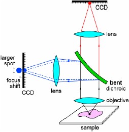
Figure 2: A bent dichroic introduces focal shift and a change in the spot size.
Generally a small shift of the focal plane is not a problem, because a lens or a camera adjustment can be made to compensate for the shift. For example, when an imaging beam is split by a dichroic onto two different cameras (as in Fig. 2), a minor adjustment to the position of the camera associated with the reflected light path is generally possible. However, such mechanical adjustments can not compensate for a change in the size or shape of the focused spot when the flatness of the dichroic is significantly compromised. Therefore, the quality of an image formed using reflected light off of a non-flat dichroic can be significantly worse than the ideal, diffraction-limited image formed using a perfectly flat dichroic.
In our experience measuring actual dichroic beamsplitters and using optical ray-tracing analyses, the dominant contribution to non-flatness of hard-coated thin-film filters is spherical curvature, and the dominant optical aberration that results when light is reflected off such a filter at 45º is astigmatism. A collimated beam of light focused by an astigmatic lens or mirror exhibits two distinct focal planes – called the tangential and sagittal planes – and the focused spot in each plane is asymmetric, as if it is focused along only one axis of the plane, but is out of focus along the other axis. Between these two planes is a third plane that contains the smallest circular focused spot, which is commonly called the “circle of least confusion.” Though symmetric, this spot is larger than the spot that would be obtained in the absence of astigmatism in the focusing lens or mirror, thus resulting in blurring of the image.
To demonstrate and quantify this effect, measurements were made using a number of different reflecting dichroics and mirrors with the experimental setup shown in Figure 3. Four filters were chosen with a wide variation of non-flatness arising from differing radii of curvature – the residual flatness (after removing the best-fit spherical error) for all filters were excellent.
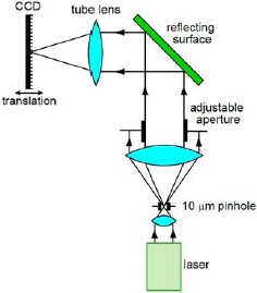
Figure 3: An experimental setup to evaluate the effect of flatness of a reflecting surface on imaging. A laser beam (532 nm) was spatially filtered using a 10μm pinhole before collimation with a single lens. The beam diameter of the collimated beam was adjusted using a variable aperture. Reflecting surfaces of different radii of curvature (3414 m, 158 m, 84 m, and 7 m) were used to steer the beams of different diameters (11 mm or 2.5 mm) using a 300 mm focal length plano-convex tube lens onto a CCD camera. The CCD camera was mounted on a linear translation stage for imaging the focal spots.
Images of the focused spot obtained from each of the four filters are shown for an 11 mm diameter beam in Figure 4. For each filter, the images were acquired at the position of best focus, as well as at the tangential and sagittal focal planes. The in-focus image quality obtained using reflection from a very flat surface (Fig. 4, top row) can deteriorate significantly (Fig. 4, bottom row) due to the astigmatism introduced by a non-flat reflecting surface. The degree of astigmatism decreases (Fig. 4, third row) or almost vanishes (Fig.4, second row) when a relatively flatter reflecting surface is used. These images clearly demonstrate that flatness of the dichroic has a significant effect on the reflected image quality. It should be noted that in these results not only the size and shape of the focal spot change, but the focal plane location is also different for the different radii of curvature of the reflecting surfaces (see Section 3 below).
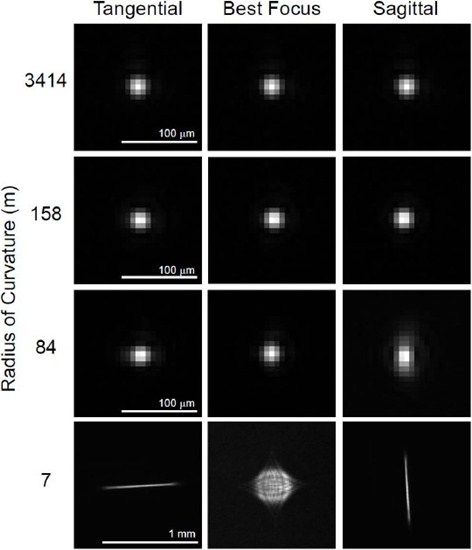
Figure 4: Images of the focused spot from an 11 mm diameter beam reflected off of dichroics of different flatness and focused onto a CCD detector using a 300 mm focal length tube lens. Images were acquired for the best-focus position as well as at the tangential and sagittal focal planes. Size bar for 7 m radius of curvature dichroic is 1 mm; all other size bars are 100μm. The intensity distributions from these images are plotted as 3D surface plots in Figure 10 (see Appendix).
It should be noted that the diameter of the illumination beam that impinges on a dichroic is generally much smaller than an imaging beam (emission signal) in most applications. For example, a laser beam reflecting off of a dichroic beamsplitter in a TIRF microscope is generally only about 1 mm to perhaps at most several mm in diameters. Since the focal spot size is significantly determined by the beam diameter (see Section 3), further experiments were conducted to observe the effect on spot size when reflecting surfaces of different radii of curvatures were used. Results based on a 2.5 mm diameter beam are shown in Figure 5. As seen in this figure, the size (and shape) of the best-focus spot does not appear to change nearly as dramatically as it does with the larger diameter beam in Fig. 4. The variation in spot sizes is also practically negligible between tangential and sagittal focal planes.
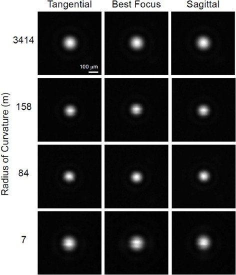
Figure 5: Images of the focused spot from a 2.5 mm diameter beam reflected off of dichroics of different flatness and focused onto a CCD detector using a 300 mm focal length tube lens. Images were acquired for best-focus position as well as at the tangential and sagittal focal planes. Size bar is 100μm. The intensity distributions from these images are plotted as 3D surface plots in Figure 11 (see Appendix).
It was pointed out above that in addition to degradation of the spot size and shape, reflection off of a non-flat dichroic also causes an appreciable shift in the focal plane relative to that obtained from reflection off of a perfectly flat mirror. Even though a small focal shift can be compensated in many situations (as noted above), there are cases in which a focal shift cannot be tolerated. For example, when a laser beam is reflected off of a dichroic beamsplitter in a TIRF microscope, the beam must be focused at the back focal plane of the objective. A significant focal shift or a change in the focal spot size caused by a bent dichroic placed in the excitation light path can make it difficult to achieve TIRF, especially if the microscope has a limited ability to adjust the collimation of the laser beam. A non-flat dichroic can also cause a similar problem in a structured-illumination microscope with broadband excitation, in which the mask must be imaged in the excitation light path onto the sample. Due to mechanical constraints it might be impossible to image the grid onto the sample plane, or at least to achieve a good image with the objective positioned to acquire a good image of the emitted light. A similar problem can also occur in confocal instruments that require sufficiently flat dichroics to enable imaging of pinholes at desired focal planes.
3. Analysis of the effects of non-flat dichroics
Given that a dichroic mirror may be used to steer the excitation light or the emission signal to a desired location, evaluation measures are needed to find out whether a dichroic mirror is sufficiently flat for a given application. For example, as observed in Section 2, beams of different diameters may require different flatness specifications. It should be noted that since thin-film coatings can themselves cause bending of the dichroic mirror, the substrate flatness before coating is not a sufficient criterion for evaluation of the performance of the filter. Therefore the flatness requirements for a dichroic should be specified for the finished, coated substrate.
Focal plane shift
When light is reflected off of a spherically curved surface with radius R, the light is focused as if it were transmitted through a lens of focal length
R/2. If the light is subsequently focused by a different lens of focal length f (and where we assume f << R/2), the reflection off of the curved surface causes
the focus to shift by an amount ![]() relative to the focus position resulting from reflection off of a
perfectly flat surface. Based on a simple first-order optics approximation, the relative focal shift is
relative to the focus position resulting from reflection off of a
perfectly flat surface. Based on a simple first-order optics approximation, the relative focal shift is 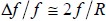 Thus, to maintain a relative focal shift
![]() below a certain required value, the radius of curvature of the bent filter surface should
exceed
below a certain required value, the radius of curvature of the bent filter surface should
exceed

For example, suppose a laser beam is reflected off of a dichroic beam splitter before being focused to a spot at the sample plane by a 40X, 0.75 Numerical Aperture (NA) microscope objective, which has a focal length of f = 5 mm (assuming a 200 mm focal length of tube lens), and suppose we want to keep the focal shift ![]() below 5μm, or the relative focal shift below 0.1%. Then the radius
of curvature R of the dichroic must be greater than about 10 meters.
below 5μm, or the relative focal shift below 0.1%. Then the radius
of curvature R of the dichroic must be greater than about 10 meters.
When working with Gaussian beams (often an excellent model for a laser beam), the depth of focus is quantified by the “Rayleigh Range,” which is the distance from the beam waist (smallest focused spot) to the point where the waist has
increased by a factor of ![]() Practically, the Rayleigh Range is a good measure of depth of focus
because a beam (or image point) focused to a location within one Rayleigh Range of the waist still appears to be in focus. If we use the criterion that the focal shift should be less than one Rayleigh Range in order to be considered negligible,
then the radius of curvature of a reflecting filter in front of a focusing lens should exceed
Practically, the Rayleigh Range is a good measure of depth of focus
because a beam (or image point) focused to a location within one Rayleigh Range of the waist still appears to be in focus. If we use the criterion that the focal shift should be less than one Rayleigh Range in order to be considered negligible,
then the radius of curvature of a reflecting filter in front of a focusing lens should exceed

where D is the diameter of the beam at the focusing lens and  is the wavelength of light. Note that the required radius of curvature is independent of the focal length of the lens.
As an example, for a 1 mm diameter 488 nm laser beam, the radius of curvature of the dichroic should be greater than about 3 meters. Semrock’s Laser Flatness/RWE dichroic beamsplitters are generally specified with a maximum beam diameter,
D, for which the focal shift is less than one Rayleigh Range at the edge wavelength of the beamsplitter. For instance, the Di02-R488-25x36 is a BrightLine® Laser Dichroic, and it is specified to have less than one
Rayleigh Range of focal shift for a 488 nm laser beam as large as 2.5 mm in diameter. For a 1 mm diameter beam, the focal shift would be less than 1/6th of the Rayleigh Range. For advanced microscopy applications our Super-resolution / TIRF Flatness
dichroic beamsplitters [7] provide optimal solutions for much larger diameter beams, by minimizing reflected wavefront distortions.
is the wavelength of light. Note that the required radius of curvature is independent of the focal length of the lens.
As an example, for a 1 mm diameter 488 nm laser beam, the radius of curvature of the dichroic should be greater than about 3 meters. Semrock’s Laser Flatness/RWE dichroic beamsplitters are generally specified with a maximum beam diameter,
D, for which the focal shift is less than one Rayleigh Range at the edge wavelength of the beamsplitter. For instance, the Di02-R488-25x36 is a BrightLine® Laser Dichroic, and it is specified to have less than one
Rayleigh Range of focal shift for a 488 nm laser beam as large as 2.5 mm in diameter. For a 1 mm diameter beam, the focal shift would be less than 1/6th of the Rayleigh Range. For advanced microscopy applications our Super-resolution / TIRF Flatness
dichroic beamsplitters [7] provide optimal solutions for much larger diameter beams, by minimizing reflected wavefront distortions.
As an imaging example, consider a 40X, 0.75 NA microscope objective for which the beam diameter is about 7.5 mm. Thus the radius of the dichroic must exceed about 160 meters in order to observe no noticeable focal shift. Most dichroics are not this flat, and thus in general there is a noticeable focal shift for light reflected off of a dichroic relative to a perfectly flat mirror. However, as pointed out above, this type of focal shift is generally easily accommodated.
Many of the aberrations in imaging that result from wedge error and wavefront errors in thinfilm interference filters [3] can be tightly controlled by selecting the best available glass substrates. In fact, the simplified single-substrate approach enabled by ion-beam sputtering technology allows for the utmost in control of substrate-induced aberrations. However the inherent bending introduced during the thin-film coating manufacturing process can alter the original flatness specifications of the substrate. Fortunately, this bending can also be controlled with appropriate choice of coating materials, substrate, and overall filter design. Furthermore, precisely controlled manufacturing processes that produce highly repeatable coatings are critical to achieving flat filters. The resulting dichroic beamsplitters are ultimately limited by a very small amount of spherical bending due to manufacturing uncertainties.
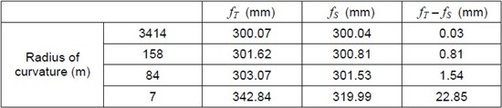
Considering the astigmatism introduced by a non-flat dichroic with a small amount of spherical bending, the location of the two main focal planes (Figs. 4 & 5) are given by the tangential and sagittal focal lengths,fT and fS, respectively [4]:
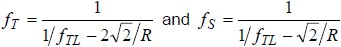
where fTL is the focal length of the tube lens (see schematic in Fig. 3). An obvious way to quantify the astigmatism is to measure the separation between the tangential and sagittal focal planes – the larger the separation, the greater the astigmatism. Using Eqs. (3) and (4), we can generate the curves shown on the graph in Figure 6, illustrating the dependence of this separation on radius of curvature for different tube lens focal lengths.
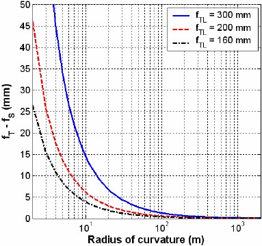
Figure 6: A change in the radius of curvature of the dichroic mirror affects the degree of astigmatism. fT and fS are the tangential and sagittal focal lengths, respectively, and fTL is the focal length of the tube lens.
Specifically, for a 300 mm focal length tube length (corresponding to the experimental imaging conditions used to produce the results in Figs. 4 and 5) the following table summarizes the locations of the tangential and sagittal focal planes for different radii of curvature of the reflecting surfaces.
Spot size change
As noted above, the non-flatness of the dichroic mirror not only changes the location of the focal plane, but also the size of the image in the focal plane may be significantly affected. For an astigmatic beam, a simple first-order optics calculation can be used to show that the geometric spot size, or diameter of the “circle of least confusion,” DCis given by
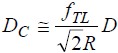
where D is the diameter of the beam and R is the radius of curvature of the reflecting surface (Fig. 3). Eq. (5) indicates that the beam diameter is directly proportional to the spot size. For the experiments presented in Figs. 4 and 5, the calculated geometric spot sizes are given in Table 2.
Table 2: Radius of curvature of the reflecting surface and the beam diameter (in Fig. 3) significantly affect the spot size for a given imaging setup. This table gives the theoretical geometric spot size limited by a simple ray optics analysis, and does not take into account the diffraction limit.
Even though this simple geometric calculation can provide a reasonable estimate of spot size for relatively larger sizes, smaller spot sizes are limited by diffraction of light due to its wave nature. The size of the Airy disc [5] is a widely accepted criterion for the evaluation of the diffraction-limited spot size. For the experimental conditions applicable to Figs. 3 – 5, the ideal diffraction-limited spot sizes are 77.88μm and 17.7μm for the 2.5 mm and 11 mm diameter beams, respectively. The variation of geometric spot size as a function of radius of curvature for various beams diameters is plotted in Figure 7. As shown in this figure, diffraction-limited spot size limits the requirement of the sufficient radius of curvature for an application.
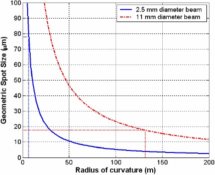
Figure 7: Theoretical geometric spot size changes as a function of the radius of curvature. The horizontal dotted lines denote the size of the Airy disc (diffraction limit) and the vertical dotted lines represent the corresponding desired minimum radius of curvature of the reflecting surface in Figure 3 to ensure that the astigmatism-limited spot size is below the diffraction-limited spot size. The focal length of the tube lens is assumed to be 300 mm.
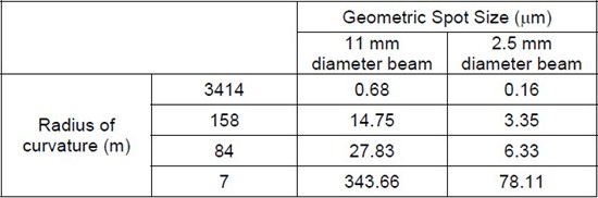
In order to ensure that the spot size is not appreciably affected by astigmatism, the diameter of the spot size determined strictly by geometric optics at the “circle of least confusion” should be comparable to or smaller than the diffraction-limited spot size (Airy disc). This criterion leads to the following requirement for the radius of curvature of the dichroic,
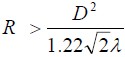
where D is the beam diameter and is the wavelength of light. Once the beam diameter and the radius of curvature are known, the flatness specification can
be specified in terms of waves (for a given beam diameter). The center to edge deflection ![]() is given by (to second order)
is given by (to second order)

Therefore, in order to ensure that there is no noticeable effect of astigmatism, the flatness of the dichroic specified in terms of center to edge deflection over the beam area is approximately given by
 is the wavelength of light that is reflected off of the dichroic in the system (and where we have approximated
 ).
).The above analysis considers approximately only the effects of astigmatism, which as we have pointed out is the dominant aberration. We can model more thoroughly what results when light is incident at 45º and is subsequently reflected off of a dichroic beamsplitter with a slight bend. Third- and higher-order aberrations (including the dominant stigmatism) degrade the quality of a focused spot size (for a collimated beam) after a focusing lens or of an image after an imaging lens. Using standard optical modeling software (like ZEMAX or Code V® by Optical Research Associates), we can calculate the geometric RMS spot size in the absence of diffraction that results from reflection off mirrors with varying radii of curvature.
The plot in Figure 8 is based on a typical epifluorescence microscope configuration, assuming a perfect point source at the sample location, imaged onto the image plane (e.g., CCD surface) by an ideal 40X, 0.75 NA objective and a tube lens with a 200 mm typical focal length. The resulting beam diameter is 7.5 mm. The reflection off of the dichroic is assumed to occur mid-way between the objective and the tube lens. The field of view of the system is assumed to be limited by a 20 mm diameter field size at the camera plane. The light is assumed to have a wavelength of 510 nm (peak of GFP emission). For comparison, the diffraction-limited spot size that would result from a perfect objective and tube lense and a perfectly flat dichroic is 16.6 μm.
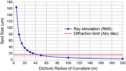
Figure 8: Spot size changes with a change in the radius of curvature of the dichroic. This example shows a ray optics calculation of the RMS spot size (absent diffraction) in a typical epifluorescence microscope configuration, with a 40X, 0.75 NA objective and a 200 mm focal length tube lens.
For the above example, the effects of ray aberrations (dominated by astigmatism) that result from the non-flat dichroic become less than that of diffraction when the radius of curvature exceeds about 50 meters. Note that the simple astigmatism analysis summarized by Eq. (6) suggests the radius of curvature for this case should be larger than about 64 meters, showing close agreement between the detailed ray aberration analysis and the simple astigmatism model.
The required minimum radius of curvature from Eq. (6) for a number of other objective-tube lens combinations that are common in fluorescence microscopes are summarized in Figure 9. The required minimum radii vary from a few tens of meters for the higher magnification objectives (with smaller beam diameter) to as high as about 50 to 100 meters for the lower magnification objectives (with larger beam diameter). Note that to calculate the beam diameter for an objective with a specified magnification and NA, it is necessary to know what tube lens focal length is assumed to achieve the stated magnification. The beam diameter is given simply by [6]
where M and NA are the objective magnification and numerical aperture, and fTL is the tube lens focal length.
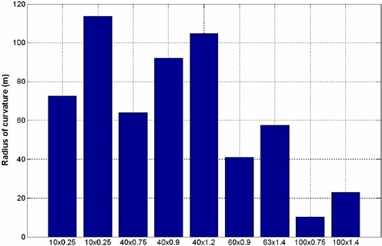
Figure 9: Desired radii of curvature of an “Image-splitting Flatness dichroic” for different objective and tube lens combinations (Magnification x NA of each objective is listed). Tube lengths of (left to right) 160, 200, 200, 200, 160, 200, 160, 200, and 160 mm were assumed. Calculations based on Eq. (6) where the beam diameter D is calculated using Eq. (9). Results correspond to an emission signal at a wavelength of 510 nm (GFP emission).
4. Comparison of actual images
Images of fixed cells were acquired using a modified microscope setup that was designed to evaluate the effect of dichroic flatness on image quality. The emission optics (including the CCD camera) of a standard epifluorescence microscope was removed from its body and the reflecting surfaces of different radii of curvature (used for the experiments reported above in Figs. 4 and 5) were used to steer the emission signal from the microscope onto the CCD detector. The principle of operation of this imaging setup was similar to the one described in Figure 3, except that the collimated beam was generated by the objective lens used to collect the fluorescent signal from the sample. For each reflecting filter, the objective focus was adjusted to achieve the clearest possible image. The resulting images are shown in Figure 10. When the reflecting surface does not have a sufficiently large radius of curvature (right image), significant blurring is introduced in the acquired image due to astigmatism. However when a dichroic of sufficient flatness is used (as demonstrated in the left three figures) then imaging quality is not compromised.
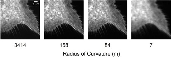
Figure 10: Images of F-actin in bovine pulmonary artery endothelial cells (Fluo Cells prepared slide #1 from Invitrogen) captured using a modified Olympus BX41 microscope. The emission signal from the microscope was reflected using surfaces of different radii of curvature. A 40X, 0.75 NA objective and 200 mm focal length tube lens were used in this experiment. The desired radius of curvature of the dichroic in order to avoid image degradation is about 64 meters. Size bar is 2 μm.
Concluding remarks
Reflected image quality can be worse than the ideal diffraction-limited response for dichroics that are not perfectly flat, though it should be noted that the true spot size at the image plane can be appreciably larger than the diffraction-limited spot size in an actual system. Nevertheless, care should be taken to select properly optimized, flatter dichroic beamsplitters when working with reflected light. Dichroics designed to reflect laser light ("Laser" or "Super-resolution / TIRF" [7] Flatness dichroics) ensure negligible focal shift for laser beams up to several mm in diameter even for most demanding applications such as Super-resolution and TIRF microscopy utilizing large diameter beams. Dichroics designed to reflect imaging beams ("Image-splitting" grade of flatness dichroics) have the most extreme flatness requirements, since they must effectively eliminate the effects of astigmatism for beams as large as 1 cm or more. For complete listing of Image-splitting dichroics review Product Page.
References
[1] T. Erdogan, New Optical Filters Improve High-Speed Multicolor Fluorescence Imaging, BIOPHOTONICS, March, 2006.
[2] D. Axelrod. Light microscopy in biology, chapter 11. Oxford University Press, Oxford, UK, 1999.
[3] J. Rietdorf and E.H.K. Stelzer. Handbook of biological confocal microscopy, chapter 3. Oxford University Press, Oxford, UK, 2006.
[4] F.R. Jenkins and H.E. White. Fundamentals of optics. McGraw-Hill, 4th edition, 1981.
[5] D.B. Murphy. Fundamentals of light microscopy and electronic imaging. John Wiley and Sons, Inc., NY, USA, 200.
[6] R. Juskaitis. Handbook of biological confocal microscopy, chapter 11. Oxford University Press, Oxford, UK, 2006.
[7] M. Delay, S. Perry, J. Kircher, P. Prabhat, Maximizing the Performance of Advanced Microscopes by Controlling Wavefront Error Using Optical Filters
Authors
Prashant Prabhat, Ph.D. and Turan Erdogan, Ph.D.
Acknowledgements
Ligang Wang, Steven Brown, Ezra Milby & Amanda Valek-McDonald