Build Your Own Fluorescence Filter Set
Despite the availability of “standard filter sets” (a combination of optimally designed exciter, dichroic and emitter filters) offered by optical filter manufacturers, it is not uncommon for researchers to build their own “custom filter sets” comprised of unique combinations of otherwise standard individual filters. Custom sets can be more optimal for unusual fluorophores or for very specific imaging conditions.
What key criteria should you consider when building a custom optical filter set?
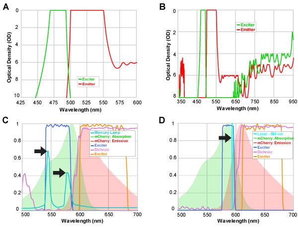
It is important to understand common pitfalls and considerations in building such custom filter sets. For example, one of the most common problems to occur is the leakage of excitation light into the emission channel, thereby preventing observation of the relatively weak fluorescent signal. Figure 1A illustrates this key criterion in designing a custom filter set – one that is often overlooked by researchers when building their own sets. It is recommended that the combined blocking of the exciter and emitter at the crossover point should be at least OD 7 or 8. This ensures that excitation light does not overwhelm the fluorescence in the emission passband.
In general, to ensure high contrast, the exciter and emitter combination should have high blocking within the passband of the complimentary filter (Figs.1A and B). Also in order to prevent damage to the sample or to the detector (or eyes) there should be sufficient combined blocking at other wavelengths, some of which can be in the exciter and some in the emitter (Fig. 1B). Generally the combined blocking should be significant at all wavelengths where the light source has appreciable power or the detector sensitivity is appreciable.
Of course, the basic considerations in designing a filter set should also be met as well as possible. For example, the exciter and emitter edges should be as close together as possible, and each of their passbands should overlap with the absorption (for the exciter) and the emission (for the emitter) spectra of the fluorophore. The dichroic beamsplitter edge wavelength as well as reflection and transmission bands should be well aligned with the crossover wavelength and the exciter and emitter passbands, respectively. When a filter set is used in a multicolor imaging application with other fluorophores and filter sets, then the edge locations (or bandwidths) of the exciter and emitter filters need to be optimized to reduce crosstalk.
While it is possible to perform detailed calculations of the signal and signal-to-noise ratio associated with a given filter set and light source, sample, and detector parameters, at the end of the day designing a filter set is still highly subjective since there are many other experimental conditions which influence the choice of the best filter set. For example, even for imaging a given fluorophore the filter sets for a laser based system or for a broadband-illuminated system are different (Fig.1C and 1D).
Partner with our Semrock Optical Filters Team
Given the complexity of requirements for designing a filter set, some of the important design criterion may be overlooked by researchers or at times certain information such as design tolerances associated with individual filters may not be easily available. Therefore it is recommended to contact the filter experts at Semrock to verify whether a combination of filters can be used together as a set.