Fluidics Tech Tips
Tech Tips presents very specific technical topics that will maximize the performance of our products, including accuracy and precision. The Tech Tips are brief and well-illustrated for easy reading.
Air in the sample loop can cause instantaneous system pressure drop that eventually returns to a normal level. Air causes the pressure to drop when the injector moves from the LOAD to the INJECT position. When large sample loops (>100 µL) are partially loaded, air present in the needle port tube is pushed into the sample loop (see Figure 1). Air can also enter the sample loop from siphoning, which occurs when the vent line is higher than the injection port. In either case, upon injection, the system pressure collapses the air bubble, causing pressure to drop momentarily. A pressure drop in the system caused by air results in changes in retention time, artifact peaks, and affects column performance.
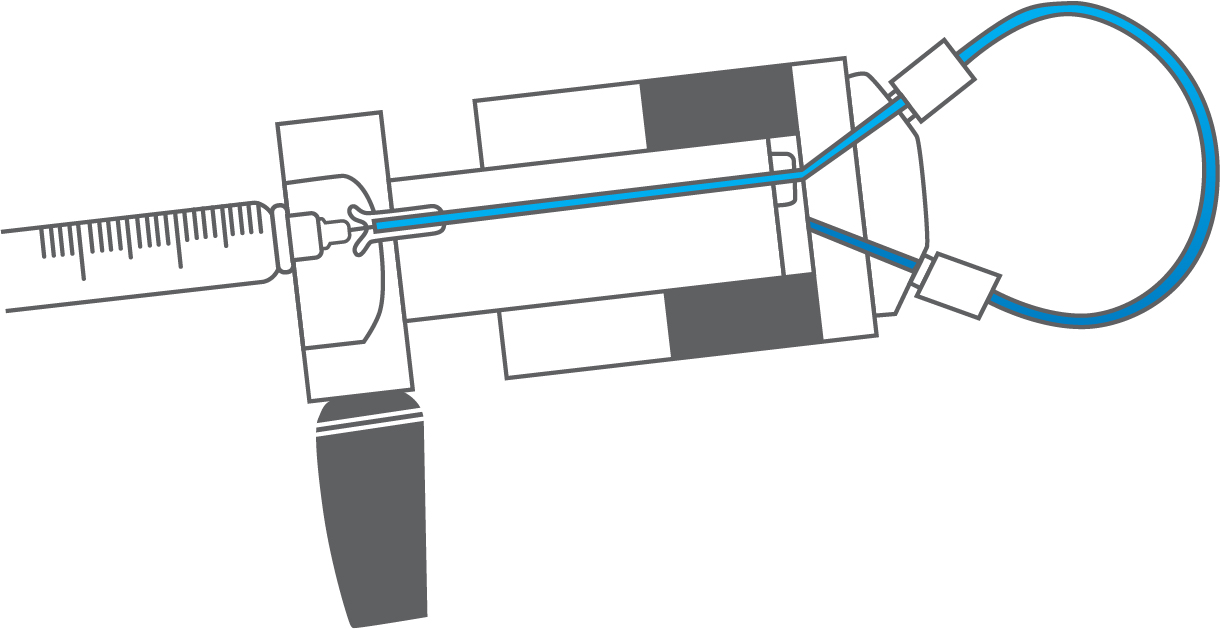
Figure 1: Air (white) present in the needle port tube is pushed by the syringe during loading into the sample loop.
Pressure drops can be avoided by removing the air in the needle port tube. Do this by flushing about 1 mL of mobile phase with a luer syringe with needle port cleaner. Keep the needle port tube filled with mobile phase by occasional flushing. Adjust the vent line(s) so that the outlet is at the same horizontal level as the needle port (see Figure 2).
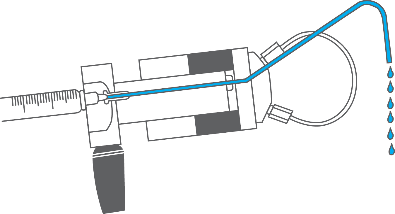
Figure 2: Pathway of the flushing mobile phase using the needle port cleaner when the injector is in INJECT.
PEEK tubing can be used instead of stainless steel tubing in most applications. PEEK is inert to almost all organic solvents and is biocompatible. Unlike metals, plastics are viscoelastic and, therefore, the yield strengths are not well defined. Many factors affect the burst pressure of PEEK tubing. PEEK tubing will burst at a lower pressure when you:
- Increase the inside diameter.
- Increase the temperature.
- Increase the time of exposure.
- Increase the concentration of organic solvents.
- Expose tubing to specific solvents. DMSO, THF, and methylene chloride cause the PEEK tubing to swell. Concentrated nitric acid and sulfuric acid weakens the tubing.
Suggested Maximum Pressure for PEEK Sample Loops
| Tube, OD | Tube, ID | Sample, Loop | Water, (1) | 1:1, ACN/Water | 100%, ACN | 100%, THF | 100%, IPA | |
|---|---|---|---|---|---|---|---|---|
| 1/16″ | 0.007″ | 5 µL | >5500 | >5500 | 4000 | 2500 | >5000 | |
| 1/16″ | 0.010″ | 10, 20 µL | 5500 | 5500 | 3500 | 2500 | 5000 | |
| 1/16″ | 0.020″ | 50, 100,, 200 µL | 4500 | 4500 | 3000 | 1500 | 4000 | |
| 1/16″ | 0.030″ | 0.5, 1.0, 2.0,, 5.0, 10 mL | 3500 | 3500 | 3000 | 1500 | 4000 | |
| 1/8″ | 0.062″ | 2.0, 5.0 mL | 4500 | 4500 | 4000 | 2500 | 3000 | |
| 1/8″ | 0.080″ | 10, 20 mL | >5000 | >5000 | 2000 | 1000 | 2500 |
Leaks cause valuable sample loss. Nobody wants that! The key to the valve holding pressure is the integrity of the sealing surfaces. If there is a scratch on the sealing surface or the needle seal in the rotor seal is damaged, a leak may appear. It is also important to realize what appears to be a leak can instead be a result of siphoning. The following are the three most common situations in which fluid leaks occur:
- If fluid leaks out of the needle port only while loading the loop (i.e., while pushing down on the plunger of the syringe), the problem is most likely that the needle seal or the needle port fitting in the loop filler port is not gripping the syringe needle tightly enough to prevent leakage around the syringe needle. Tighten the needle seal grip by pushing down on the needle guide (see Figure 1) or replace the needle port fitting to make a tighter grip on the needle. The tightening reduces the hole diameter of the needle seal and port fitting.
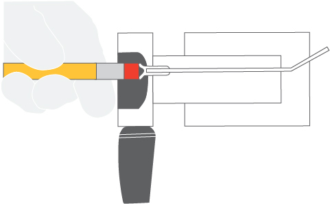
Figure 1: To reform the needle seal, push the eraser end of a pencil against the needle guide.
- If fluid leaks continuously from the needle port or vent lines and/or from the stator-to-stator ring interface, the rotor seal and/or stator face assembly needs to be replaced. Scratches on the rotor seal or cracks in the stator face assembly allow mobile phase to escape and cause cross-port leakage. See IDEX Health & Science Rotor Seals and Stators.
- If fluid leaks from the needle port and/or vent lines but eventually stops, the cause is most likely siphoning and not a leak. Siphoning occurs if the vent lines are lower or higher than the needle port. Adjust the vent line(s) so that the outlet is at the same horizontal level as the needle port to prevent siphoning. See Figure 2.
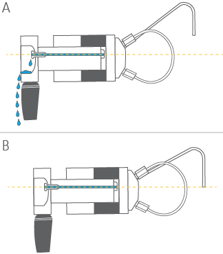
Figure 2: Needle port level compared to the level of vent line outlet: (A) Siphoning occurs when the vent line outlet is above the needle port level; (B) Siphoning does not occur if the vent line outlet is the same horizontal level as the needle port.
With front-loading injectors, it is important to use the correct needle when loading the sample loop. An incorrect needle will damage the valve and can cause poor reproducibility. When the needle is too short, the tip will not reach the needle seal. When the needle is too small in diameter, the seal will not grip tightly enough. Needles with a beveled tip can damage the rotor seal and stator face assembly (see Figure 1B).
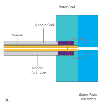
Figure 1A: A square-cut needle stops against the stator face assembly.
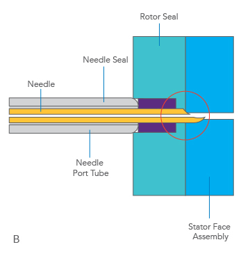
Figure 1A: A square-cut needle stops against the stator face assembly.
The needleshould be #22 gauge, and 90° point style (square cut end). Model 3725 requires a #16 gauge needle. Never use a beveled, pointed, or tapered needle. Needle specifications are not critical when using a Loop Filler Port to load the sample loop. However, it is important to tighten the needle port fitting around the needle if using a syringe needle with a slightly smaller diameter than 0.7mm (0.028″). If the loading method used is complete-filling, a syringe without a needle can be used. A syringe fitted with a needle port cleaner can be used with a front-loading valve (Figure 2A) or with a loop filler port (Figure 2B). Be sure to use a proper syringe needle.
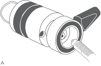
Figure 2A: Syringe fitted with needle port cleaner (Part # 7125-054) loading a front-loading valve (Model 7725).
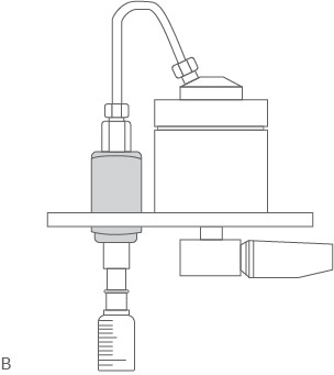
Figure 2B: Loading a loop filler port (Part# 7012).
The standard rotor seal in many IDEX Health & Science manual valves is made from a Vespel® blend. This polyimide has low wear and high chemical resistance. Vespel tolerates a pH range of 0 to 10. Solutions more basic than pH 10 dissolve Vespel, which damages the rotor seal. If you use any solutions above pH 10, IDEX Health and Science recommends a PEEK-blend rotor seal. PEEK offers a high-chemical resistance and versatility and will tolerate the entire pH range from 0 to 14. Tefzel®-blend rotor seals may be appropriate for some applications. See IDEX Health & Science rotor seals.
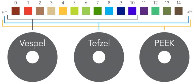
Figure 1: pH range of various rotor seal materials. pH colors are for illustration only.
Genuine IDEX Health and Science rotor seals are matchless in performance and product life. For a quarter of a century, they have exceeded the needs and expectations of chromatographers. Our rotor seals are products of rigid manufacturing and quality assurance procedures before they are incorporated into our valves or shipped to our customers. Only genuine IDEX Health & Science parts ensure the continued precision performance of our Science valves. Our engineers develop exacting product specifications and designs, including the factory-installed rotor seal ring, which optimizes rotor seal efficiency. IDEX Health and Science rotor seals must pass our tougher-than-real-world standards of performance. Our rotor seals are made from proprietary-blended polymers, formulated specifically for resistance to repetitive chemical and physical stresses of the entire 0 to 14 pH range. Tested under actual laboratory conditions, rotor seals fully meet the demanding requirements of day-to-day manual instrument use as well as the operating conditions found in today’s automated laboratories.
Vespel and Tefzel are registered trademarks of E.I. DuPont.
Partial-Filling
Use the partial-filling method if you need to conserve sample or if you want to vary sample volume frequently. In partial-filling, the syringe sets the volume injected onto the column. There is no sample waste, and the volume injected onto the column is equal to that dispensed from the syringe. Reproducibility is 1.0% relative standard deviation (RSD). The volume of the sample loaded is limited to half the sample loop volume. For example, the most you can load into a 200µL sample loop is 100µL. See Figure 1. This limitation is due to the manner in which fluids move in tubes. Fluidic movement in tubes affects reproducibility. See Tech Tip 7.

Figure 1: The sample loop can fill up to half the loaded volume in the partial-filling method.
Complete-Filling
Use the complete-filling method if you have a sufficient amount of sample with which to work, if you do not vary sample volume, or if you need high reproducibility. In complete-filling, the loop sets the volume loaded onto the column. You use excess sample (two to five loop volumes) to replace all the mobile phase in the loop. See Figure 2. Change the loop to vary the sample volume. Reproducibility is typically 0.1% RSD for loop sizes > 5µL. Accuracy is limited as loop volumes are nominal.
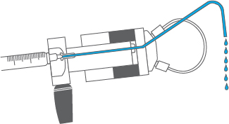
Figure 2: The sample loop is filled in excess in complete-filling method.
“Which method should I use and which sample injectors use this method”
There are two types of injectors available: dual mode and single mode. Dual mode injectors allow both partial- and complete-filling, whereas single mode injectors allow only complete-filling.
If you are collecting experimental data, sample is scarce, and/or you want to use different sample volumes, a dual-mode injector with a large volume sample loop is appropriate. Only dual-mode injectors allow the partial-filling method with which you can easily vary your volumes (up to half your sample loop volume) by setting the syringe volume. Once you begin routine analysis and/or you have an abundance of sample, either a dua-mode or single-mode injector is appropriate. Both types of injectors allow the complete-filling method with which you fill the sample loop in excess. Complete filling maximizes the reproducibility of your results.
“Why I load only up to half of the volume of the loop in partial-filling method?”
Sample occupies 2µL of loop for every 1µL loaded from the syringe. For example, 10µL of sample spreads out over the entire length of a 20µL loop. Any more sample loaded will overflow the end of the loop and exit out to waste. Reproducibility is poor because the volume of sample in the loop is different from the known volume originally loaded by your syringe.
Fluid spreads in a parabolic shape through a tube instead of moving in one plug because the velocity is different at the center of the tube than at the walls. The velocity at the center of the tube is twice the average velocity, and near the wall the velocity is almost zero, creating a parabolic shape. This fluidic movement is called laminar flow. See Figure 1.
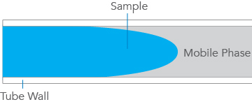
Figure 1. Schematic of sample flow through mobile phase between tubing walls.
In dual-mode injectors (see Tech Tip 6) the sample from the syringe needle loads directly into the sample loop. The sample volume is known since there is no sample waste. The laminar flow phenomenon accounts for the shape of the plot as shown in Figure 2. Note that the plot has three regions:
a) Partial-Filling Region
When the volume dispensed is less than half the loop volume, the curve is linear. Sample has not reached the end of the loop. Within this region, performance depends on the syringe and operator.
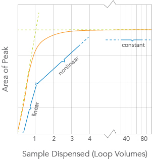
Figure 2. Sample mass (observed peak area) vs. volume of sample dispensed from the syringe, in units of loop volumes, injected onto the column from a IDEX Health & Science dual mode injector such as Model 7725.
b) Nonlinear Region
When the volume dispensed is between half the loop volume and about two loop volumes, the curve is nonlinear. Sample is lost from the loop, so reproducibility is poor. If you dispense a volume equal to the loop size, you are in this region of poor performance.
c) Complete-Filling Region
When the volume of sample dispensed is several loop volumes, the loop contains only pure sample undiluted by residual mobile phase. Within this region, reproducibility is highest.
In the single mode injectors, the sample must pass through a connecting passage before it reaches the sample loop. Since some of the sample dispensed from the syringe remains in the connecting passageway, an unknown amount enters the sample loop. Therefore, single mode injectors achieve high reproducibility only by using the complete-filling method. See Tech Tip 6.
Stainless Steel
Stainless steel sample loops are supplied with fittings that are unswaged onto the tube. It is important that the loop be completely bottomed in the injector port before the ferrule is swaged onto the tube. The depth of the tubing holes may vary slightly from port to port and from valve to valve. A fitting made up in one port may leave a small cavity in another port. The cavity causes high dispersion and peak distortion such as fronting, tailing, or broadening. It is good practice to label loop ends so they will be replaced in the same, respective ports that were used in swaging the ferrules. Hint: swaging ferrules separately on each side, into each respective valve port, makes loop installation easier.
To install the sample loop:
- Take one end of the loop and place the nut (1) and ferrule (2) onto the tubing (3) with the threaded portion of the nut and tapered portion of the ferrule toward the end. See Figure 1A.
- Insert the tubing into port (4). Confirm that the tubing is bottomed in the valve port as shown in Figure 1A.
- While firmly pressing down on the tubing, hand-tighten the nut as tight as possible.
- With our IDEX Health & Science Wrench, designed especially for fittings, tighten 1/4 turn past fingertight. Remove the loop to confirm that the ferrule is swaged onto the tube.
- Repeat steps a-d with the other end of the loop while the swaged end remains outside the valve port. See Figure 1B.
- Reinstall each end of the loop to their respective ports. See Figure 1C.
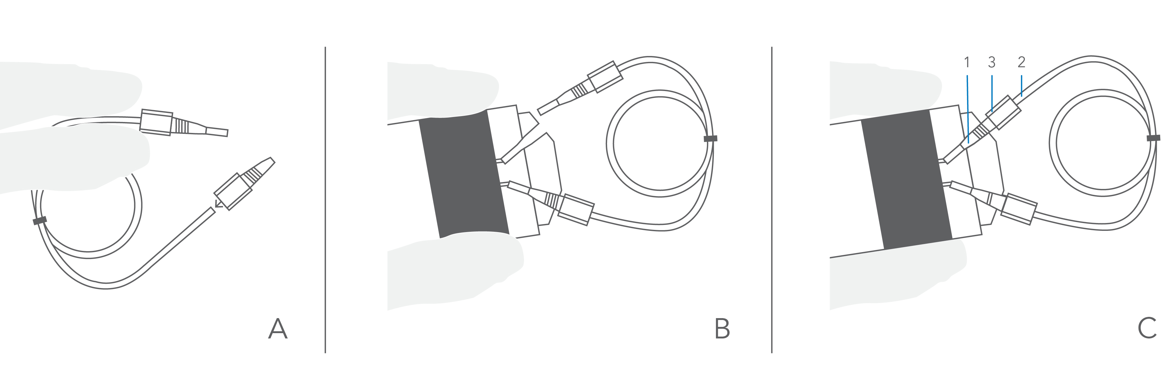
Figure 1: Cut-away views (A, B, and C) of stainless steel sample loop installation.
PEEK Fittings and PEEK Tubing
PEEK loop installation requires steps a–c in the stainless steel section above. Fingertightening of PEEK fittings is adequate to make a leak-free connection. The slotted backside of the ferrule (1) is squeezed down onto the tube (2) by the mating conical surface in the nut (3). See Figure 2. The nut and ferrule can both be reused many times. Unlike ordinary fittings, the unique PEEK design, specifically the angles and surface contacts between the ferrule and nut, prevents the nut from gripping the ferrule and twisting both the ferrule and the tube during tightening. Otherwise, such twisting stresses the PEEK tubing and lowers the pressure rating of the tubing.
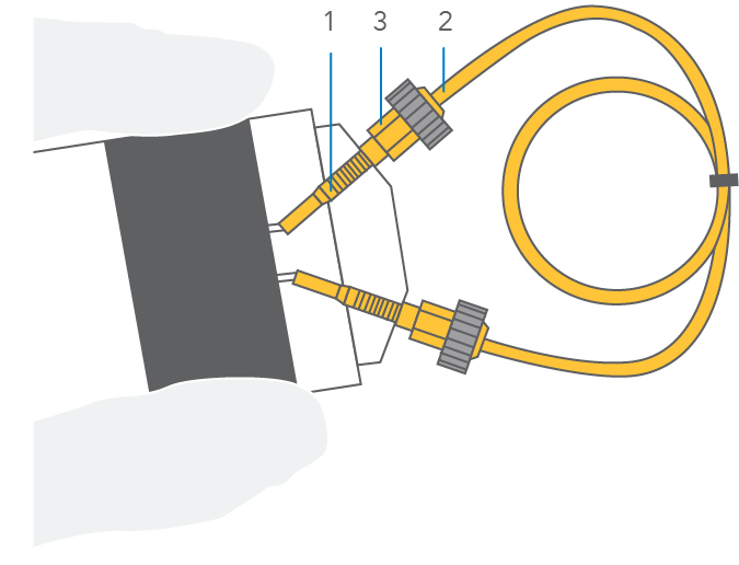
Figure 2: Cut-away view of PEEK sample loop installation.
Stainless Steel (and titanium)
A good square-cut, burr-free end on tubing is important for use in your system. The square-cut makes a flat surface for the tube to make contact against the bottom of the valve port. Without this contact, a cavity will form that causes high dispersion and peak distortion such as fronting, tailing, or broadening.
To install the tubing:
- Place the nut (1) and ferrule (2) with threaded portion of the nut and tapered portion of the ferrule onto the tubing (3). See Figure 1A.
- Insert the tubing into the valve port (4). Confirm that the tubing is bottomed in the valve port as shown in Figure 1B.
- While firmly pressing down on the tubing, fingertighten the nut as tight as possible.
- With the IDEX Health & Science Wrench, designed especially for fittings, tighten 1/4 turn past fingertight. Remove the fitting to confirm that the ferrule is swaged onto the tube.
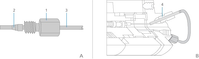
Figure 1. Cut-away view of stainless steel fittings installation.
PEEK Fittings and PEEK Tubing
PEEK tubing is flexible and easy to cut with a sharp blade. Confirm that the ends are clean and straight and that the inner passage is fully open. To install the tubing follow steps a–c in the stainless steel section above. Fingertightening of 1/16″ PEEK fittings is adequate to make a leak-free connection. The 1/8″ PEEK fittings need to be wrench-tightened. The slotted backside of the ferrule (1) is squeezed down onto the tube (2) by the mating conical surface in the nut (3). See Figure 2. The nut and ferrule can both be reused many times. Unlike ordinary PEEK fittings, our unique PEEK design, specifically the angles and surface contacts between the ferrule and nut, prevents the nut from gripping the ferrule and twisting both the ferrule and the tube during tightening. Otherwise, such twisting stresses the PEEK tubing and lowers the pressure rating of the tubing.
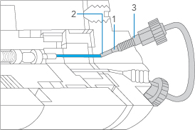
Figure 2: Cut-away view of PEEK fittings installation.