Fittings Primer
To properly describe the type of fitting necessary for a particular connection, several things must be taken into account. General descriptive terms include the geometry of the receiving port (coned or flat-bottom); the size tubing for which the fitting is designed; and a mechanical designation of the threads on the nut portion of the fitting (e.g. 10-32, 1/4-28, etc.). Beyond these general categories, fittings may be classified by the overall dimensions (length, maximum diameter, etc.) and the type of material from which they are manufactured: stainless steel or polymer-based.
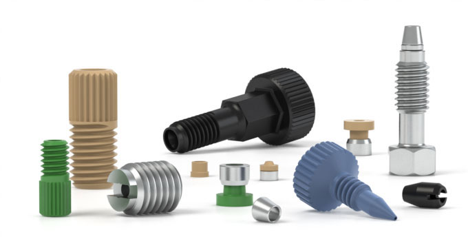
We offer a wide and diverse selection of fittings to meet your systems requirements. We have implemented more stringent testing protocols and generous safety margins to our ratings to ensure your safety. Explore our Fittings for HPLC, UHPLC and low pressure applications.
Stainless Steel Fittings
Although restrictive in use and non-universal in application, stainless steel fittings remain the most popular fitting used on standard HPLC systems today, due to their solvent inertness and high-pressure holding abilities. These fittings usually
come in a conical configuration, requiring special care to be taken in choosing the proper fittings for any given mating port.
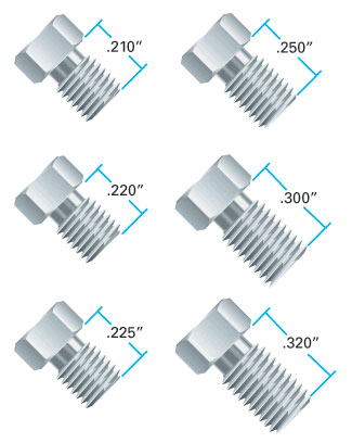
In general, male stainless steel nuts vary in overall length and thread length, and these two dimensions are often manufacturer-specific [Figure 4].
Figure 4:
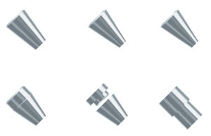
Also, stainless steel ferrules are available in a variety of shapes [Figure 5].
Figure 5:
Therefore, to ensure proper operation and long life from the chosen fitting, it is best to use fittings specifically designed for use with a particular manufacturer’s port.
Besides the array of fittings available for use with different manufacturers’ equipment, stainless steel fittings exhibit one attribute which separates them from polymer-based fittings; in order to use them properly, the ferrule portion of the fitting must be swaged-or permanently attached-to the tubing it is connecting. To do this properly, we recommend the following procedure:
Place the nut and ferrule, in that order, on the tubing [Figure 6]. Place the loosely assembled fitting into a mating port, and tighten the nut finger tight. While ensuring the tubing is bottomed out inside the mating port, tighten the nut with a wrench an additional 3/4 of a turn. The ferrule should now be permanently attached to the tubing.
Figure 6:
PLEASE NOTE: Because the ferrule is permanently attached to the tubing and because of standard machining tolerances, we highly recommend that any pre-swaged stainless steel fitting only be used in the mating port into which it was initially swaged. Failure to do this may result in dead volume or solvent leakage.
Additionally, for proper tightening of a pre-swaged stainless steel fitting into its mating port, we recommend wrench tightening only an additional 1/4 to 1/2 of a turn past finger tight, followed by subsequent monitoring of the connection for any leaks. Should leaking occur, simply continue to tighten the fitting a little at a time until the leak stops. Also, should it become necessary to tighten the fitting more than one complete revolution past finger tight, IDEX Health & Science recommends that the fitting be replaced, as excessive tightening is typically indicative of a damaged product.
Polymer-Based Fittings
Unlike their stainless steel counterparts, polymer-based fittings are typically non-restrictive and fairly universal in function. And while stainless steel fittings remain the most popular fitting used with HPLC systems, polymer-based fittings are
continuously gaining in popularity not only due to their near-universal application but also based on their ease of use.
Because of the nature of polymer-based fittings, the same degree of care does not have to be taken when choosing the proper fitting to mate with a specific manufacturer’s receiving port. Primarily, the only two characteristics of the fitting which must be known are the geometry (coned or flat-bottom) of the receiving port and the thread dimensions.
Also, and again unlike stainless steel fittings, polymer-based fittings do not permanently attach to a piece of tubing and usually do not require the use of any tool (besides your fingers!) to properly tighten and use. Additionally, these fittings often come in a variety of polymers, including PEEK™, Teflon®, Tefzel®, Delrin®, PPS, polypropylene, and others, for maximum cost and solvent resistance flexibility.
Interchangeability
There are many different fittings to work with in HPLC. Many fittings look similar making interchangeability a real problem. Let’s see if we can offer some clarification.
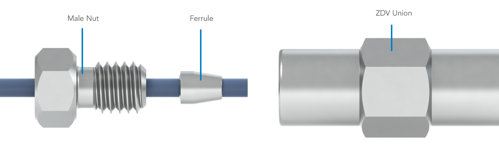
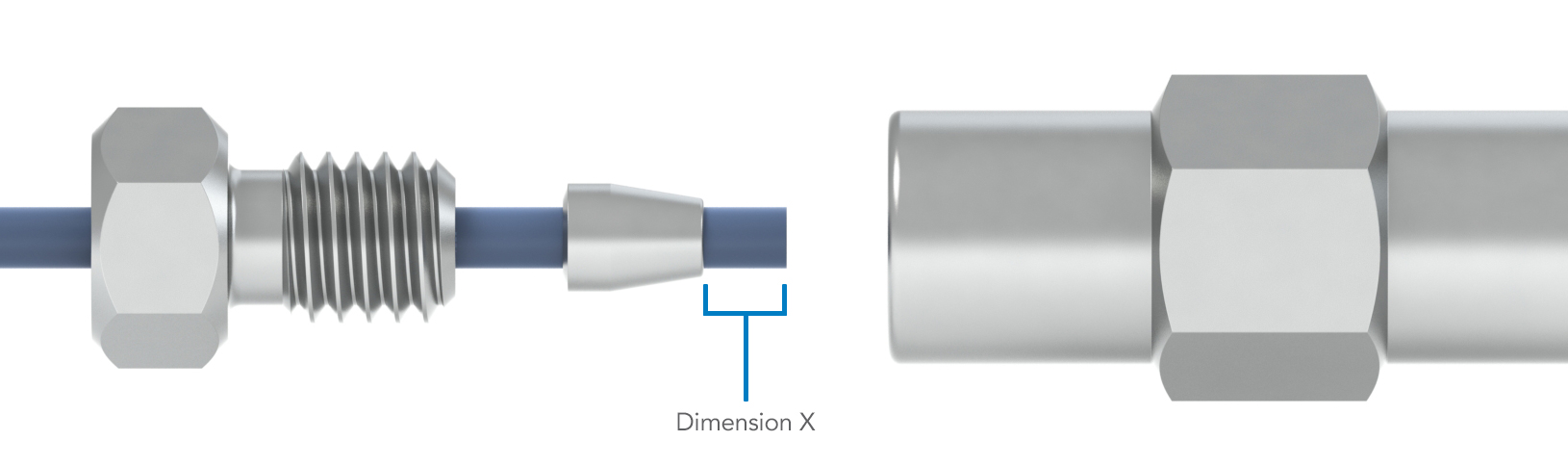
Take a zero dead-volume union, male nut, and ferrule from one manufacturer [Figure 1a]. Put the male nut and ferrule on a piece of 1/16″ OD stainless steel tubing. Insert the tubing, ferrule, and nut into the ZDV union. Be sure the tubing bottoms out in the union. Swage the ferrule onto the tubing by tightening the male nut finger tight, and then a 3/4 turn with a wrench. Now remove the male nut, ferrule, and tubing from the fitting. Measure the distance from the end of the ferrule to the end of the tubing [Figure 1b]. Let’s call this Dimension X.
Figure 1A:
Figure 1B:
Dimension X varies from one manufacturer to another [Figure 2]. Dimension X can also vary from the same manufacturer due to variation in tolerances. Because of these typical variances seen among the array of manufacturers, we generally recommend new fittings, new ferrules, and new connections each time assemblies are connected, although such care is not necessary in all cases.
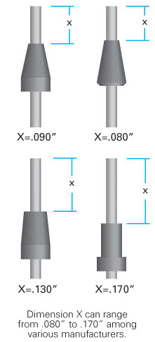
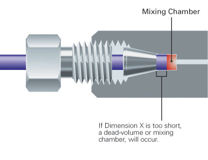
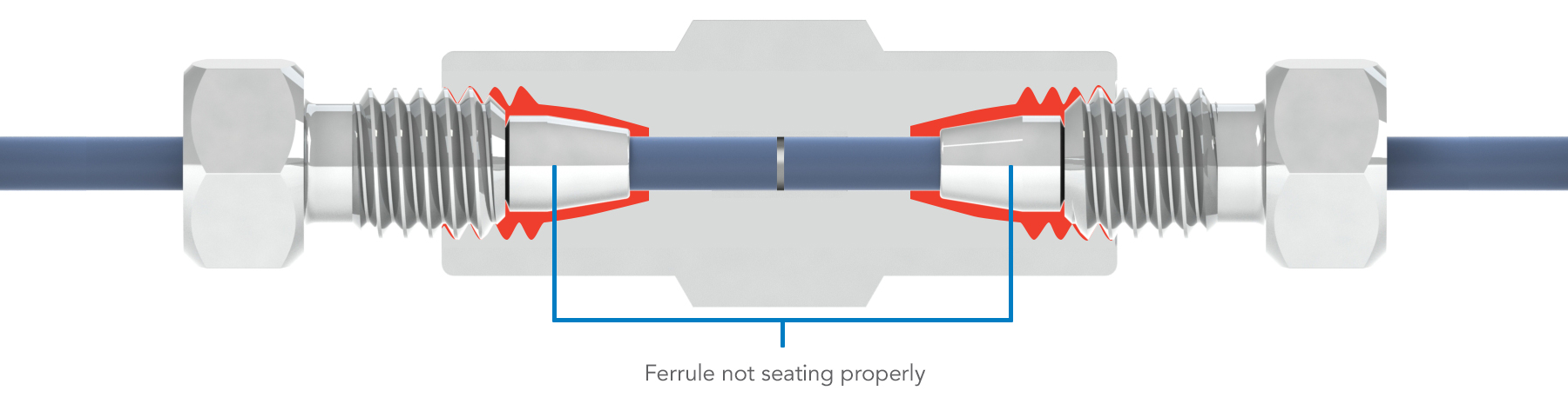
Figure 2: Dimension X can range from 0.080″ to 0.170″ among various manufacturers. Here’s an example: Valco, Parker, and Swagelok® zero dead-volume fittings are interchangeable at the initial assembly. However, dimension X is long with a Waters® fitting. If a ferrule has been swaged in a Waters fitting, and you then insert it into an IDEX Health & Science fitting, the ferrule will not seat and will leak [Figure 3a]. Dimension X is short with our fitting. If the ferrule has been swaged in one of our fitting and you insert it into a Waters fitting, the tubing will not bottom out and you will have a dead volume/mixing chamber [Figure 3b].
Figure 3A:
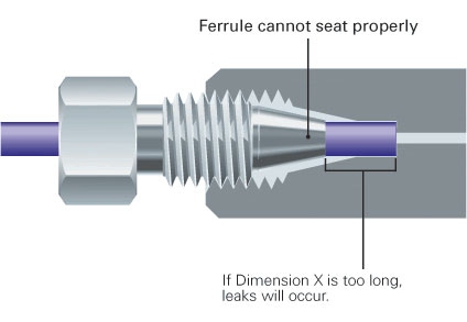
Figure 3B:
If Your Fittings Leak
Check to make sure your tubing is seated properly
When using universal Fingertight fittings, the tubing must bottom out in the fitting before the nut and ferrule are tightened. If, after tightening the fitting a gentle tug
disengages your tubing, remove fitting and try again.
The fitting may not be tightened enough
Stainless steel nuts and ferrules require a wrench to tighten them, even after repeated use. Fingertights also require a good turn with your fingers, but not with a wrench as this may damage
the fitting.
You may be using incompatible fittings
Make sure you are using a nut and ferrule that are compatible with the components of your system. To avoid this problem and ensure compatibility, use IDEX Health & Science universal Fingertight
fittings. Because the ferrule does not permanently swage onto your tubing, a Fingertight can be used over and over again with most types of systems.
Check the condition of the nut and ferrule
After repeated use, nuts (and especially ferrules) will gradually become deformed to the point of being incapable of creating the seal they were designed to make. Always keep an extra supply
of all the nuts and ferrules you are using so that you can replace them quickly and avoid unnecessary down time.
Sometimes a leaking connection has nothing at all to do with the nut and ferrule, but with the receiving port
Female fittings that have had stainless steel fittings swaged into them are especially susceptible to damage. Check the
receiving port for visible burrs or scratches and replace if necessary.
NOTE: Using fittings made of material that is incompatible with your mobile phase is a sure way of creating leaks–and possibly causing permanent destruction of the fittings.
Tell-Tale Signs Of System Leaks
Before you even see your first drip from a fitting, your system can tell you that the problem exists. The most common signs of system leaks are as follows:
- No flow or pressure
- Pump pressures up, but no flow
- Noisy baseline
- Baseline drift
While all of these symptoms could also indicate problems completely unrelated to leaking fittings, it is always easiest to start there. Not only are fitting leaks usually easy to repair, they are also the least expensive part of the system that can cause problems.
Threads
HPLC employs several thread sizes. Most common are 1/4-28, 10-32 and M6. The first two are U.S. Customary System measurements while the third, the M6, is an International Metric System designation.
U.S. Customary System
The first number indicates the diameter of the threaded portion of the nut (not the tubing diameter). Thread diameter numbers range from 1 (.073″) to 12 (.216″). Beyond .216″ the thread
description is the thread per inch count. Thus, a 1/4-28 male nut [Figure 7] has a 1/4″ (.250″) diameter thread barrel and 28 threads per inch. A 10-32 male nut [Figure 8] has a 10 (.190″) thread barrel and 32 threads per
inch, a narrower nut with a denser thread count.
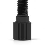
The Metric System uses a one number thread description. Metric nuts in HPLC typically have one thread per millimeter and the M simply stands for metric. The single number refers to the diameter of the thread barrel in millimeters. Thus, an M6 nut [Figure 9] is 6mm in diameter and has 1 thread per millimeter.
Figure 7: F-201 1/4-28 Nut
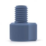
Figure 8: F-300 10-32 Nut
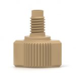
Figure 9: F-307 M6 Nut
Unions
Most plumbing in HPLC is done with 1/16″ OD (outside diameter) tubing. A union is used when it becomes necessary to join pieces of this tubing together.
There are two basic types of unions commonly used in HPLC. Terminology in HPLC is difficult due to the lack of standardization. Although, we will call the two types External Unions and Internal Unions.
External Unions
External unions have threads on the outside of the union body. Therefore, they use fittings with internal or female for the connection of tubing. The thru-holes of external unions are typically .040″ to .050″ in diameter.
This is a relatively large ID (inside diameter) for HPLC; most tubing is .010″ or .020″ ID. Why are there no external unions available with smaller thru-holes? It is a practical manufacturing consideration, it is simply too difficult to
accurately drill a long hole with a small diameter. A typical external union is shown in [Figure 10].
Figure 10: Typical external union with internally threaded fittings.
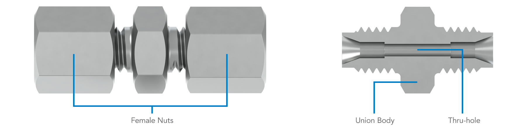
External unions are used in non-critical areas for fluid transfer; for example, they can be used between the pump and the sample injection valve where thru-hole diameter is not a factor.
External unions should not be used after the sample injection valve or before the detector. Once the sample has been introduced into the system, smaller diameters are required to prevent dead-volumes (small mixing chambers) that can seriously affect your results.
Internal Unions
Internal unions have threads on the inside of the union body, and they use male, external fittings for the connection of tubing. Internal unions have smaller IDs than external unions and are used in the more critical areas of the
HPLC system. It is in these areas, after the injection valve, that swept-volume becomes a critical situation.
Many manufacturers call their unions “zero dead-volume unions” when in reality they are small dead-volume unions. Let’s look at what a zero dead-volume union is and see how the various unions differ.
True Zero Dead-Volume Union
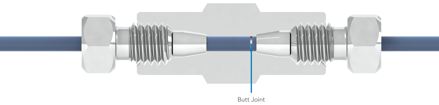
A true zero dead-volume union, or ZDV, would connect two pieces of tubing without any dead-volume, or mixing chamber, between the tubing. The tubing would butt perfectly together as shown in [Figure 11]. A connection of
this type is difficult, if not impossible, to achieve. There really is no way of knowing whether the tubing is butting together or not, or if the tubing is butting in the center of the union. [Figures 12A and 12B] demonstrates this difficulty.
Figure 11: True zero dead-volume connection.
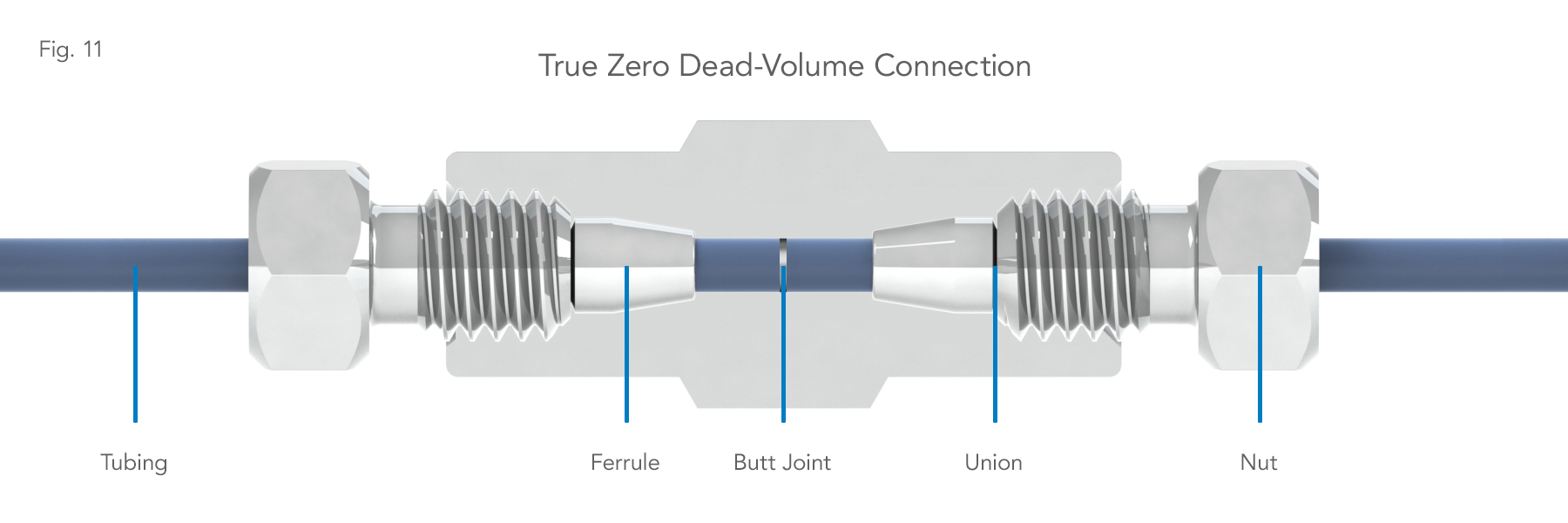
Figure 12A: The zero dead-volume connection difficulties.
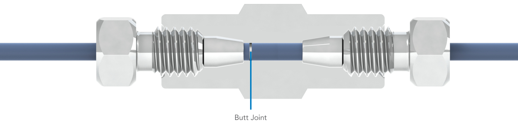
Figure 12B: The zero dead-volume connection difficulties.
Webbed Union
The problems posed by a true zero dead-volume union [Figure 13] & [Figure 14] are solved by the kind of union most manufacturers term a ZDV. Although the two pieces of tubing do not butt directly together, these unions come closest
to providing a reliable zero dead-volume connection.
Figure 13: Dead-volume occurring in a true zero dead-volume union.
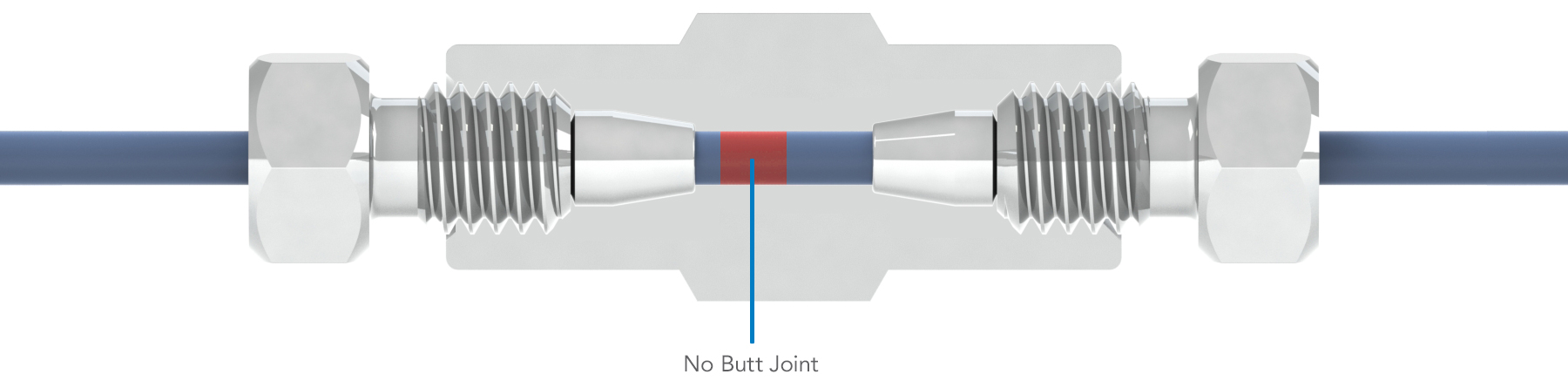
Figure 14: Leakage occurring in a true zero dead-volume union.
The union body is designed to have a thin web of material in the center [Figure 15]. A small thru-hole (matching the ID of the intended tubing) is drilled through the center of the web allowing fluid to flow from the tubing on one side of the web into the tubing on the other side.
Figure 15: The zero dead-volume union solution.
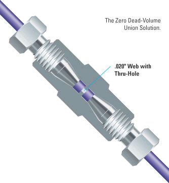
Even though this is not a true zero dead-volume union, it is a practical solution and a generally accepted alternative to a true zero dead-volume union.
Filtration
An HPLC system is a sophisticated pumping system consisting of many expensive precision components. Foreign particles introduced at any point can block and/or seriously damage one or more of these components. But by following a few simple procedures, you can protect your delicate system.
An HPLC filtration system can be looked at in five parts:
- Solvent Filtration
Pre-filter and store solvents in a vessel that allows solvent to be pumped out and sparging gas to be allowed in. An inlet solvent filter (or “sinker”) on the end of the pump inlet tube will filter the solvent again and hold the tube at the bottom of the reservoir. - Inline Solvent Filter
Since pump-seal particles can break off and block the injection valve or the column frit, use an inline solvent filter with a 2µm filter disc immediately after the pump to help prevent this. - Sample Filtration
Before injection, samples should be filtered. One option is to use a disposable sample filter attached directly to your injection syringe; however, the choice of filtration devices depends upon the volume of the sample. - Precolumn Filter
A 2µm or 0.5µm filter between the injector and the column will insure no particles suspended in the mobile phase reach the guard or analytical columns. The internal volume of a precolumn filter will generally be lower than that of an inline filter, due to concern about volume after the injector. The precolumn filter traps any material that would otherwise end up on the frit at the entrance to the column. So why have a precolumn filter with a column frit already there? Because changing the main column frit risks disturbing the column packing, which can ruin your column. The precolumn filter is therefore a risk-free, inexpensive “insurance policy” to protect your expensive column. - Guard Column
Guard columns also protect the analytical column. They are typically packed with the same material as the analytical column of the same inner diameter. It acts as a chemical filter, removing strongly retained materials that would otherwise foul the main column.
Check to make sure your tubing is seated properly
When using universal Fingertight fittings, the tubing must bottom out in the fitting before the nut and ferrule are tightened. If, after tightening the fitting a gentle tug disengages your tubing,
remove fitting and try again.
Interested to learn more about fittings and connections?
Download our Fittings 101 Guide